You're reading the documentation for an obsolete version. For the latest released version, please have a look at mp1.5.
Servo Setup and Test
Overview
This document is intended to guide UR+ partners and Certified Systems Integrators (CSI) in the setup of a single servo drive for external rotary axis. The intended application is to drive a rotary part positioner in coordinated motion for welding.
Steps
The steps listed below, in order, are covered in this document.
Install the MotionPlus URCap
Set up the servo drive and motor with appropriate power
Connect the servo drive to the UR Controller
Power up the servo drive
Start the MotionPlus service
Modify the ServoConfig script
Run ServoTests 1,2, 3 and 4
Install the MotionPlus URCap
The MotionPlus EtherCAT master is contained in the MotionPlus URCap. It communicates with the the UR Controller over shared memory to send external axis positions from the controller to the EtherCAT drives at 2ms intervals - following the 500Hz clock cycle of the UR controller.
Install the URCap using a USB thumbdrive inserted into the teach pendant. For more information on installing URCaps in general, please refer to this document [add reference here].
Tested Servos
We have tested the following servo drives for MotionPlus compatibility in our lab:
Yaskawa Sigma 7 Series (SigmaX coming soon)
Mitsubishi J4 and J5 Series
Nanotec PD4
Festo CMMT AS Series
HCFA Y7FB040A-S 400W
USB Ethernet Adapters
The PS5.16 and later software supports USB-Ethernet adapters with the Realtek 8153 chipset, and the ASIX AX88179 chipset. For example, both the TPLink UE300 will and the TPLink UE306 will work. These are generally available through Amazon.com.
Setup the Servo Drive
Verify that your servo drive supportes the necessary protocol. The drive should be capable of;
EtherCAT communication
DC - Distributed Clock
Cia402 Motion Control Profile
CSP - Cyclic Synchronous Positioning (mode 8)
Adjustable cycle time to 2ms (most drives offer this with options for 1ms, 2ms, 4ms)
E-Stop input, optional but recommended. Should be wired in with the UR Control E-Stop safety I/O.
Once you verify that the drive meets this criteria, check for the following capabilities of your servo motor:
Motor has a positioner encoder (absolute or relative). If relative, homing will be required.
Motor has brakes to stop the rotary positioner from moving when power is removed.
Your servo drive should be securely mounted to a fixed base for testing. The shaft (with or without gearbox) should be able to turn freely. Do not attach any load to the drive for these early tests. A qualified technician should connect the drive to its power source, ensure appropriate grounding, and provide the appropriate DC power source for the drive electronics. UR does not provide support or guidance in the installation and wiring of servo drives - please consult with your distributor or servo drive manufacturer.
Connect to the Servo Drive
The UR Control Box (series 5.x) should be connected to the servo drive using an ethernet cable. This cable can be a standard Cat5e cable with RJ45 connectors, or the cable provided by the servo drive manufacturer. There are two ways to connect to the UR Control box.
a. USB-Ethercat: An approved USB to ethernet adapter can be used, connected to the highspeed USB port on the controller. See the end of this document for recommended USB adapters.
b. Ethernet primary port. This is the preferred connection, since USB adapters can experience latency problems that cause issues with some servo drives. When using the primary port, refer to the technical note on how to swap ethernet devices eth0 and eth1.
Power Up the Servo Drive
Apply the mains (AC) and the DC power to the servo drive. The Servo Drive should come up, ready to connect. If the servo drive display shows a fault, this must be resolved before proceeding further. For example, some servos require that you clear the encoder backup fault if you have had the drive stored and without power for some time.
Start the MotionPlus Service
In Polyscope, on the installation page, click on the side tab for MotionPlus. Select the network device from the drop down list, choosing eth1 as your device of choice. Click the [Start] button to begin the MotionPlus service. This starts the service but does not start the EtherCAT master. That is done using a URScript command in the upcoming steps.
Modify the Servo Config Script
The examples scripts include a file named servoconfig.script. You must first modify this file to match your particular drive.
Set the value for your encoder resolution (counts per revolution). It’s important to get this right as it affects the positioning and speed of the motor turning
Set the value for the feed constant to 2*PI for a rotary axis if not already set. You may have to changes the sign (+/-) later to ensure that the motor turns in the proper direction.
Set the axis type to revolute if not already set.
Save your changes to the servoconfig script.
Servo Tests Program Setup
Create a new program
Turn off the ‘Loop forever’ option
Add the servo config script
Add the servo test scripts 1, 2, 3 and 4.
Turn off scripts 2, 3 and 4. We will only run one test at a time, disabling the others while we run.
Servo Test 1 - Basic Servo Move
This first test will check to see if the ethercat communications are working and that the servo motor can rotated one turn in each direction, with a speed of 1 revolution per second.
Power up the robot from the Teach Pendent (main screen, lower left button)
Run the program
You should see the motor rotate one turn counter clockwise (view facing the end of the motor shaft our gear output), then rotate two turns clockwise, and finally rotate back to the starting position.
The speed should be 1 revolution per second.
If the motor rotates in the opposite direction, then edit the servoconfig script and change the sign for the feedconstant to -2*PI.
If the motor rotates faster or slower than expected it is possible that you have the wrong setting for encoder counts per revolutions. Check your servo motor manual and consult with your servo manufacturer.
If the servo drive issues a fault or the MotionPlus displays and error, please consult the MotionPlus TroubleShooting document for diagnostic techniques.
Servo Test 2 - Homing
Once you have completed Step #1, you are ready to test homing. MotionPlus (release 1.0) only supports homing at the current position. This effectively resets the internal encoder count to zero immediately without moving the motor. More advanced homing techniques with limits switches are coming in a later update to MotionPlus.
Power up the robot from the Teach Pendent (main screen, lower left button)
Disable Servo Test1 and enable Servo Test 2
Run the program
The homing test is in two parts. The first is without homing, then the same motion executed with homing.
For the first part, you should see the motor perform three revolutions - rewinding to zero after each turn.
In the seconnd part, the program will home to zero between revolutions, so there should be no rewind - just three revolutions in the same direction with a pause of 1 sec between each one.
Servo Test 3 - Calibration
In order to perform coordinated motion, we need to calibrate the position of the rotary axis with respect to the robot. This is done through a calibration procedure. Follow these steps:
Power on the robot
Attach a pointing tool (see image) for the calibration procedure.
Use the built-in TCP calibration (see image) to create a TCP for the pointing tool.
Set the TCP for the pointer as default.
Add an installation variable named CAL_ROTARY_AXIS and set the value to p[0,0,0,0,0,0]. This global installation variable will store the calibration pose for the rotary axis.
On the program tab, disable Servo Test 2 and enable Servo Test 3
Run the program
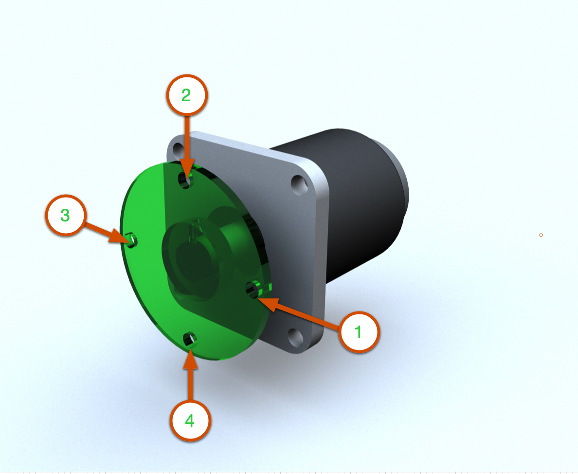
This program will instruct you to teach four points on the circumference of a circle around the motor shaft center. You will need to attach a flange to the shaft or use the gearbox output to teach the four points. The first part marks the direction of the X-axis. The second point marks the general direction of the Y-axis. The third and fourth pointes are used to compute the normal to the XY plane.
The result is the pose update of the global variable CAL_ROTARY_AXIS, used in the next step for testing coordinated motion.
Servo Test 4 - Coordinated Motion
This final step will test motion of the robot TCP and the rotary axis together. This test is quite simple - the robot TCP, close to the rotary axis will synchronize with the motion of the axis - appearing to remain fixed to the rotary direction. In this test, we command the robot TCP to frame track with the axis, then we turn the axis. We do not directly instruct the robot. This is a visual verification to check if your have calibrated the axis properly and that your servo config is also correct.
Power on the robot
Disable Servo Test 3 and enable Servo Test 4
Using Free Drive, bring the robot TCP close but not touching the motor shaft or attached flange. A distance of 5-10cm is suggested.
Adjust the speed slider on the Teach Pendant down to 10%
Be ready to stop the program immediately if the robot moves in the wrong direction - i.e. does not follow the axis rotation direction.
Run the program
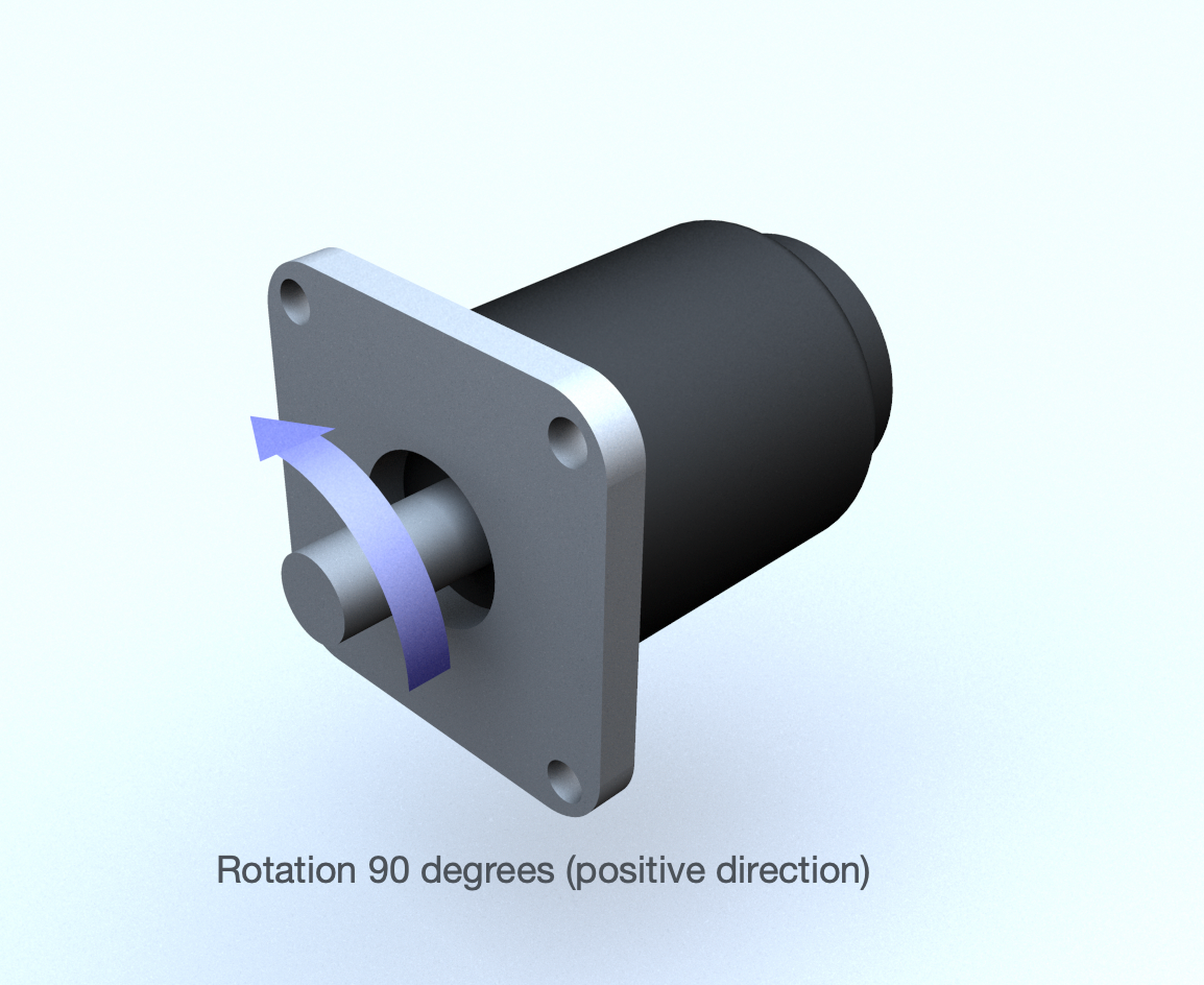
First, the servo should turn a quarter turn in the positive direction (90 degrees), back to the starting position, then a quarter turn in the negative direction (-90 degrees), then back to start.
Next, with tracking on, this motion is repeated, but this time with the TCP pointer tracking the rotary motion.
Script Examples
EtherCAT Drive Config Script
This script should be placed first within a program. See the screen shot of the teach pendant below:
#EtherCAT Drive Config Script
#This script provides the configuration for the EtherCAT drive, servo motor, gearing and encoder.

global PI = acos(-1)

POSITIONER_AXIS_TYPE = 0                # 0:rotary, 1:linear
POSITIONER_VELOCITY_LIMIT = 0.7*2       # rad/s
POSITIONER_ACCELERATION_LIMIT = 0.1*100 # rad/s^2
POSITIONER_ENCODER_RESOLUTION = <ENCODER>
POSITIONER_FEED_CONSTANT = 2 * PI       # make sure +Z points out of motor
POSITIONER_GEAR_RATIO = <GEAR>
POSITIONER_ZERO_OFFSET = 0

# stop EtherCAT master first, otherwise, reset_world_model may throw an error
ethercat_clear_error()
ethercat_stop(True)

reset_world_model()

# after calibration, change this to use CAL_AXIS_ROTARY
axis_position = p[0,0,0,0,0,0]
#axis_position = CAL_AXIS_ROTARY

axis_group_add("positioner", axis_position, "base")

axis_group_add_axis("positioner", "axis1", "", p[0,0,0,0,0,0], POSITIONER_AXIS_TYPE, POSITIONER_VELOCITY_LIMIT, POSITIONER_ACCELERATION_LIMIT)

ethercat_config_axis("axis1", 1, POSITIONER_ENCODER_RESOLUTION, POSITIONER_GEAR_RATIO, POSITIONER_FEED_CONSTANT, POSITIONER_ZERO_OFFSET)

ethercat_set_parameter("dc_enable", True)
ethercat_start(10)

if (ethercat_is_axis_in_fault_state("axis1")):
    textmsg("FAULT in: ", "axis1")
    if(ethercat_reset_axis_fault("axis1")):
        textmsg("FAULT cleared")
    end
end
ethercat_enable_axis("axis1")
Slow Turn Rotary Script
# Test1 Slow turn of the servo
popup("Ready for Test1?", title="Servo Test1", blocking=True)
popup("Moving axis to ZERO", title="Servo Test1", blocking=True)

axis_group_movej("positioner", [0], 0.1, 0.1)
popup("Moving axis to +90, -90, ZERO", title="Servo Test1", blocking=True)
axis_group_movej("positioner", [d2r(90)], 0.4, 0.4)
sleep(0.5)

axis_group_movej("positioner", [d2r(-90)], 0.4, 0.4)
sleep(0.5)

axis_group_movej("positioner", [d2r(0)], 0.4, 0.4)
sleep(0.5)
Homing Test Script
popup("Ready for Test2?", title="Servo Test2", blocking=True)
popup("Moving axis to ZERO", title="Servo Test2", blocking=True)
axis_group_movej("positioner", [0], 0.1, 0.1)

popup("Home axis to ZERO position?", title="Home Axis", blocking=True)

if (ethercat_home_axis_direct("axis1") == False):
    popup("Homing failed", title="Home Axis", blocking=True, error=True)
end

popup("Turning 3 times without homing", title="Test2-Homing", blocking=False)
i = 0
while i < 3:
   axis_group_movej("positioner", [d2r(0)], 0.4, 0.4)
   sleep(0.5)
   axis_group_movej("positioner", [d2r(360)], 0.4, 0.4)
   sleep(0.5)
   i = i + 1
end

popup("Turning 3 times with homing", title="Test2-Homing", blocking=False)
i = 0
while i < 0:
   axis_group_movej("positioner", [d2r(0)], 0.4, 0.4)
   sleep(0.5)
   axis_group_movej("positioner", [d2r(360)], 0.4, 0.4)
   sleep(0.5)
   ethercat_home_axis_direct("axis1") == False)
   i = i + 1
end
Coordinated Motion Script
# Test the positioner motion

popup("Ready for Test4?", title="Servo Test 4", blocking=True)

popup("Moving axis to HOME", title="Servo Test 4", blocking=True)
axis_group_movej("positioner", [0], 0.1, 0.1)

popup("Moving axis to +90, -90, HOME", title="Axis Testing", blocking=True)
axis_group_movej("positioner", [d2r(90)], 0.4, 0.4)
sleep(0.5)

axis_group_movej("positioner", [d2r(-90)], 0.4, 0.4)
sleep(0.5)

axis_group_movej("positioner", [d2r(0)], 0.4, 0.4)
sleep(0.5)

#set this value to clear any obstacle mounted to the shaft
#prevents the tool from colliding with the axis

distanceFromAxis = 0.06
popup("Moving TCP to position near axis", title="Axis Testing", blocking=True)
APPROACH_TRANS = p[0, 0, -distanceFromAxis, 0, 0, 0]

# place a frame with Z axis pointing down (dr2(180)) and then some distance up from the axis

add_frame("positioner_base", p[CAL_AXIS_ROTARY[0], CAL_AXIS_ROTARY[1], CAL_AXIS_ROTARY[2], 0, d2r(180), 0], "base")
movel(struct(pose=APPROACH_TRANS,frame="positioner_base"))

popup("Tracking axis rotation...", title="Axis Testing", blocking=True)
frame_tracking_enable("axis1")

popup("Moving axis to +15, -15, HOME", title="Axis Testing", blocking=True)
axis_group_movej("positioner", [d2r(15)], 0.4, 0.4)
sleep(0.5)
axis_group_movej("positioner", [d2r(-15)], 0.4, 0.4)
sleep(0.5)
axis_group_movej("positioner", [d2r(0)], 0.4, 0.4)
sleep(0.5)