You're reading the documentation for an obsolete version. For the latest released version, please have a look at mp1.5.
Manually Setting the Axis Indices and Streaming over RTDE
Brief: in this example, we demonstrate how an axis’ index can be set and how the index determines the placement of an axis’ data in the streamed target_external_q RTDE vector.
URScript API functions used in this example:
axis_group_addaxis_group_add_axisaxis_group_movej
The table below shows two examples where two axes, “axis1” and “axis2” are added to an axis group called “positioner”.
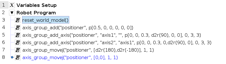
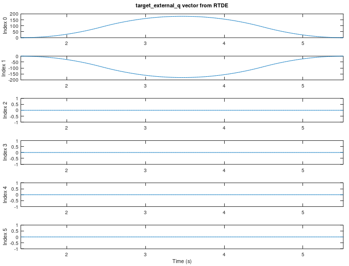
In the left example, the indices of “axis1” and “axis2” are unspecified by the programmer and are left to be decided by axis_group_add_axis. The default behavior is the next available index is used in increasing order on each call to axis_group_add_axis. In the left example, this means that “axis1” has index 0 and “axis2” will have index1. The target axis positions that are streamed over RTDE in the target_external_q vector are also plotted while the axis_group_movej command drives “axis1” and “axis2” to their 180 and -180 degree positions, respectively, and then back to their 0 positions. The target for “axis1” shows up in the 0 index location of the RTDE vector and the target for “axis2” shows up in the 1 index location.
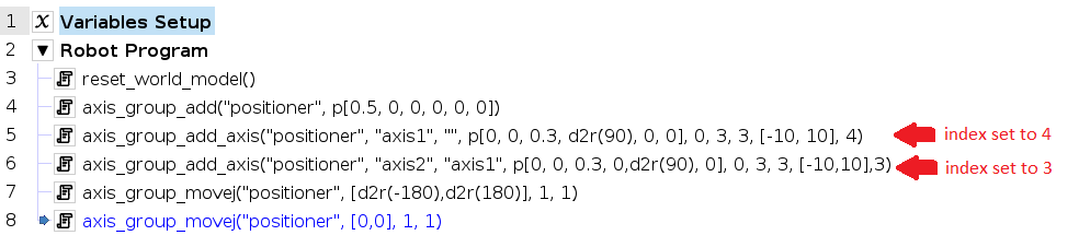
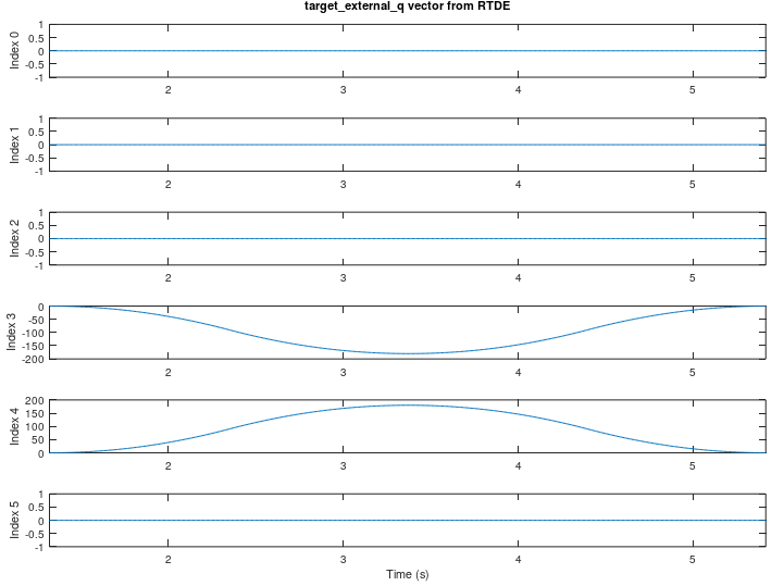
In the right example, the indices of “axis1” and “axis2” are manually set by the programmer when calling axis_group_add_axis. The programmer sets the index of “axis1” to 4 and the index of “axis2” to 3. Note how the placements of the desired axis position targets are reversed in the call to axis_group_movej. This is because axis_group_movej maps its targets in the order of increasing index, which means “axis2” now comes before “axis1” because its index is lower. The target axis positions that are streamed over RTDE in the target_external_q vector are plotted. Note how the targets for “axis1” show up in the 4 index location and “axis2” show up in the 3 index location.
Using the Default Indices |
Manually Setting the Indices |
|---|---|
|
|
|
|