SRCI setup and usage
Programming your Universal Robots cobot via your PLC may have advantages in some use cases, and the Standard Robot Command Interface (SRCI) enables that.This step-by-step guide will help you to set up and use your Universal Robots cobot with SRCI from start to finish.
Please be aware that this guide is still continuously being updated as we have more feedback from customers, enabling us to make it a better experience integrating your Universal Robots with SRCI.
Introduction
SRCI moves the entire integration of a robotic application to the PLC including the programming of the robot being integrated. With SRCI, functionality for commanding robot motions and for providing an interface for robot programming is added on top of all the common functionalities of the PLC such as workcell logic control and safeguarding. This ‘one to rule them all’ philosophy lifts the burden off the shoulders of the integrator of having to master the many ways different robots are integrated. If you are familiar with PLC programming and SRCI you can integrate any robot.
SRCI is a command-based protocol working over PROFINET. It is an open standard developed and maintained by PROFINET International. SRCI defines many commands for basic and advanced use cases. Some are mandatory and some are optional. UR SRCI implements the set of commands known as the “CORE PROFILE” and is built according to version 1.3 of the SRCI standard.
Broad Release version URCap: Supports all 29 “Profile : Core” functions and requires a paid license.
The broad release version of URcap (full version) includes the following 29 functions:
Command |
Description |
|---|---|
RobotTask |
Handles multiple mechanisms that are required for the RI to work. It must be called once per RA |
ReadRobotData |
Read robot-specific data from the RC |
EnableRobot |
Enable/Disable robot into RA power state “Enabled” |
GroupReset |
Resets and acknowledges info, warning and error messages |
ReadActualPosition |
Reads the current position of the TCP relative to the selected or currently used |
ReadActualPositionCyclic |
Reads the current position of the robot cyclically |
ExchangeConfiguration |
Reads and writes specific configuration parameters on RC that are required for the RI to work |
ChangeSpeedOverride |
Commands a speed override from the PLC to the RC |
ReadMessages |
Read pending info, warning and error messages and move them into user data block “RobotData” |
GroupJog |
Manually jog the TCP or the robot joints |
MoveLinearAbsolute |
Commands an interpolated linear movement of the robot arm to an absolute cartesian position |
MoveDirectAbsolute |
Commands movement without a specific path (PTP) of the robot arm to an absolute cartesian position |
MoveAxesAbsolute |
Commands movement without a specific path (PTP) of the robot arm to an absolute position specified in Joint Position |
GroupStop |
Aborts and deletes all active and buffered commands from the sequence buffer of the active sequence |
GroupInterrupt |
Interrupts the processing of the currently active sequence (e.g. active movements) |
GroupContinue |
Continues the processing of the currently active sequence (e.g. interrupted movements) |
ReadToolData |
Gets the offset of the tool |
WriteToolData |
Sets the offset of the tool |
ReadFrameData |
Gets a user-frame in the workspace of the robot |
WriteFrameData |
Sets a user-frame in the workspace of the robot |
SetSequence |
Set active sequence |
ReadRobotDefaultDynamics |
Read default values of robot dynamic parameters used by move commands |
WriteRobotDefaultDynamics |
Write default values of robot dynamic parameters used by move commands |
ReadRobotReferenceDynamics |
Read reference values of robot dynamics for path movement |
WriteRobotReferenceDynamics |
Write reference values of robot dynamics for path movemen |
ReadLoadData |
Read content of selected payload number |
WriteLoadData |
Change configuration of selected payload number |
ReadRobotSWLimits |
Read actual software limits of the axes |
ReturnToPrimary |
Return to path left during active interrupt |
Prerequisites
Using SRCI with your Universal Robots cobot requires several prerequisites to be met:
Siemens TIA Portal: version 16 and above.
Including SIMATIC Step 7 Professional (Required) and SIMATIC WinCC Comfort (Required for HMI simulation)
This guide will be using TIA Portal 19 with SIMATIC Step 7 Professional and WinCC Advanced.
Siemens PLC: S7-1500(F) and S7-1500S(F), SIMATIC S7-1500(F) - firmware version 2.8 or newer, SIMATIC S7-1500S(F) - firmware version V20.8 or newer.
Siemens recommends at least a S7-1515 CPU for a standard pick & place application via. SRCI.
This guide will be using an S7-1516F-3 PN/DP PLC.
Siemens SIMATIC Robot Library: [6ES7823-0RE00-3AA0]
For more information please visit SIMATIC Robot Library V1.1.0.0: Delivery Release
Siemens SIMATIC Robot Integrator: Sample project including SIMATIC Robot Library (trial version).
Please request “SIMATIC Robot Library + SIMATIC Robot Integrator” via this link
It is possible to input SRL license directly into the sample project, to continue working with full access.
SRCI URCap: SRCI is not standard functionality of your UR cobot. You need the UR SRCI URCap, and for the broad release, you need to purchase a license to activate this. Please contact your local sales representative.
PolyScope 5.15.0: PolyScope 5.15.0: Using the UR SRCI URCap requires PolyScope 5.15.0 or later. Currently, PolyScope X does not support UR SRCI. UR SRCI works with any e-Series, UR20 and UR30 cobot arm.
Supported version of PolyScope is downloadable from our download page.
Setup
SIMATIC Robot Integrator sample project
When you have downloaded your SIMATIC Robot Library (SRL), you should be able to find a compressed sample project called “SIMATIC-Robot-Integrator-SRL.zap17”, which is the foundation for this guide.
Open TIA Portal.
Press “Activate basic integrety check”.
Browse for your compressed sample project (.zap17).
Choose a folder for the project to be extracted in.
Press “Open”.
If asked to upgrade to newer version, press “Upgrade”, then “Open”.
After loading is done, press “Open the project view”.
TIA Portal PLC setup
Finding/adding your PLC’s IP address
If You have already configured PROFINET device name and IP address on your PLC, you can skip this step.
Make sure the PLC is connected locally with your PC.
In the project tree (left sidebar), go to “Online access” → <Your network adapter> → “Update accessible devices”.
If you have already configured PROFINET devicename, find the PLC’s name in here and open the tab.
If you have not already configured PROFINET devicename, look for “Accessible device” and open the tab.
In the tab, click “Online & diagnostics” → Assign IP address.
If you have not already configured PROFINET devicename, click “Assign PROFINET device name” and assign its name.
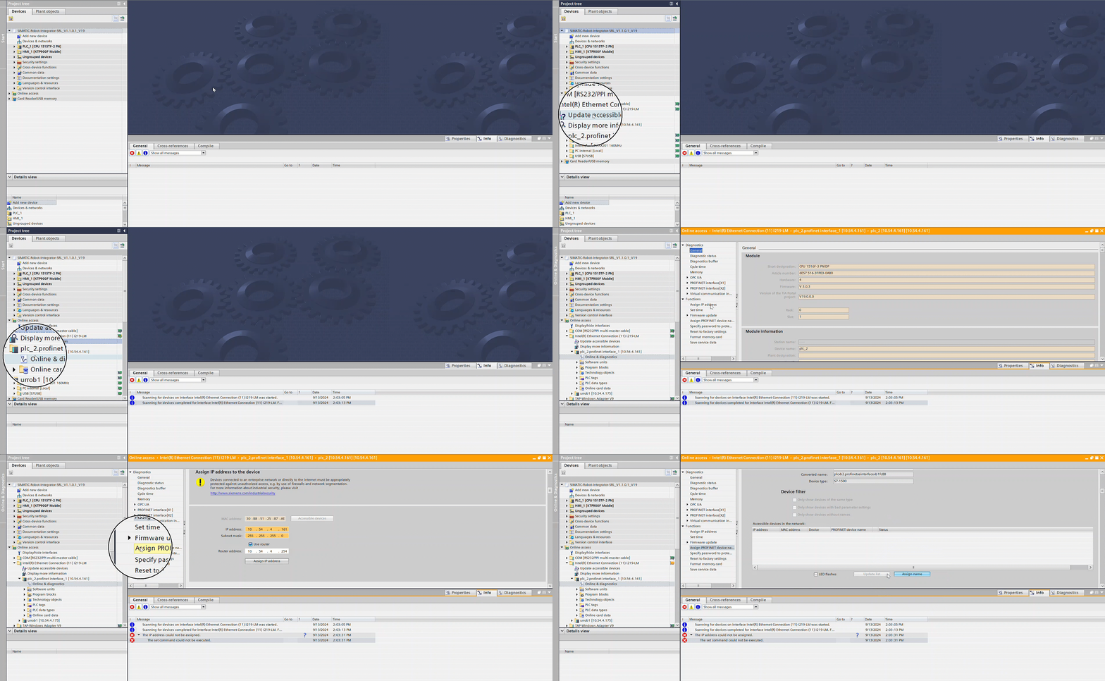
If you already know your PLC’s IP address / now have assigned it
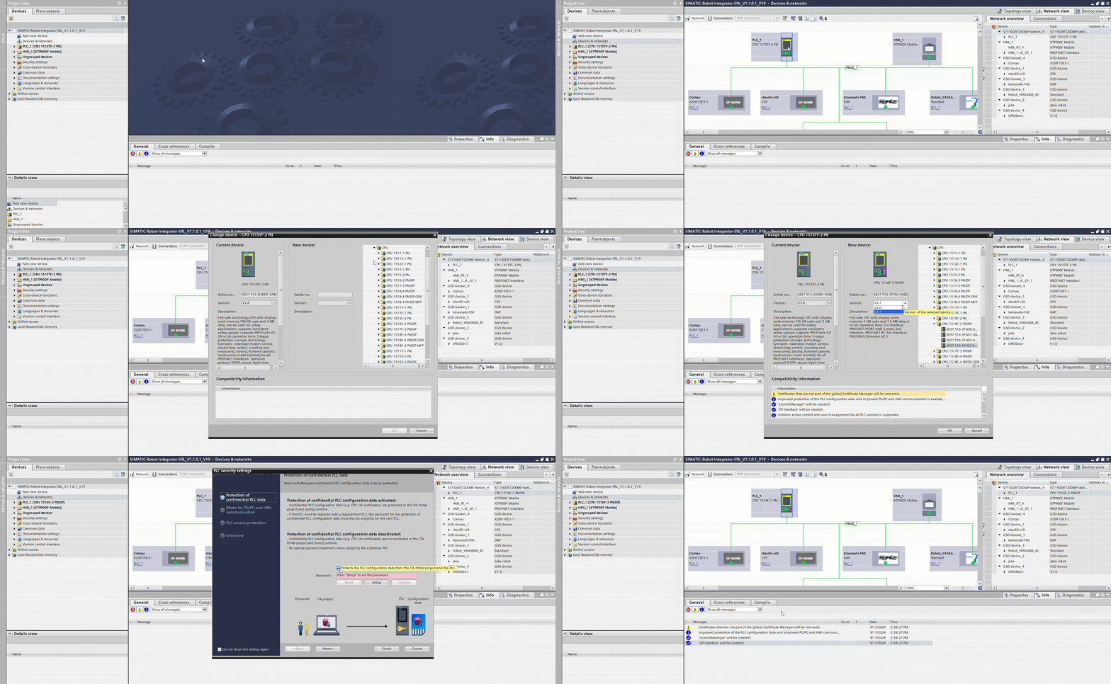
Go to “Devices & networks” in the project tree.
Right-click “PLC_1 in the network and press “Change device”.
Select your PLC from the catalog, and follow its configuration guide.
Right-click on “PLC_1” in the network again, and press “Properties”
Type in the PROFINET device name in “General”.
Now go to find the network port (For example X1) → “Ethernet addresses” and type in IP address, gateway and router.
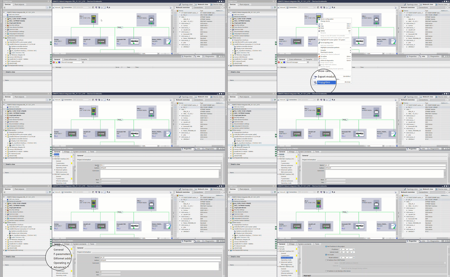
If your PLC has F-capabilities, and you want these turned on, go and turn them ON in “Properties” → “F-capabilities” and OFF if not.
This guide will not provide how to set up PROFIsafe with SRCI. Though, this is to be made in a future tutorial.
Until then, please visit PROFIsafe technical guide for e-series.
TIA Portal HMI setup
Because most of the programming in SRCI is done through the “SIMATIC Robot Integrator” (HMI), you will either need a physical HMI or a simulated HMI.
It is also possible to only use the Simatic Robot Library to program the robots “offline”, but this is a bit more advanced, and will not be covered in this guide.
If you have a physical HMI:
Go to “Devices & networks”.
Right click “HMI_1” → “Change device” → Find your PLC in the catalog, and follow the configuration guide.
In “Devices & networks”, right-click your HMI → Press “Properties” → PROFINET Interface [X1] → “Ethernet addresses” and insert the IP address, Subnet mask and router.
If you are simulating an HMI:
Go to “Devices & networks”.
Right-click “HMI_1” → Press “Properties” → PROFINET Interface [X1] → “Ethernet addresses” and press “IP address is set directly at the device”.
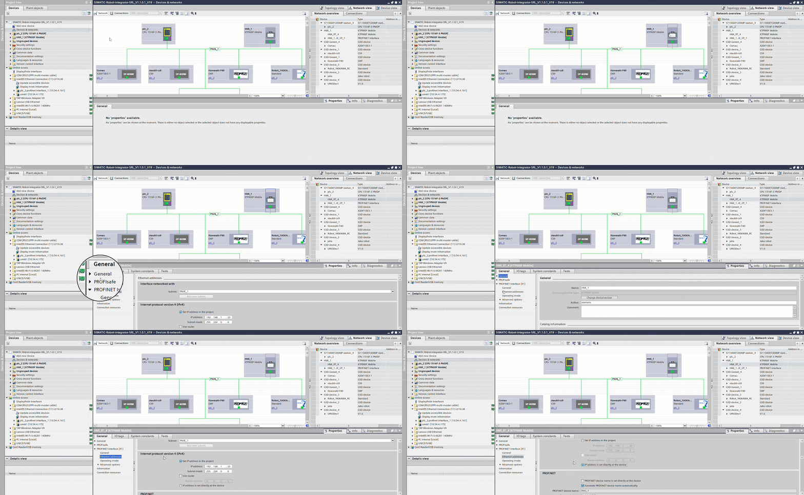
HMI PC setup
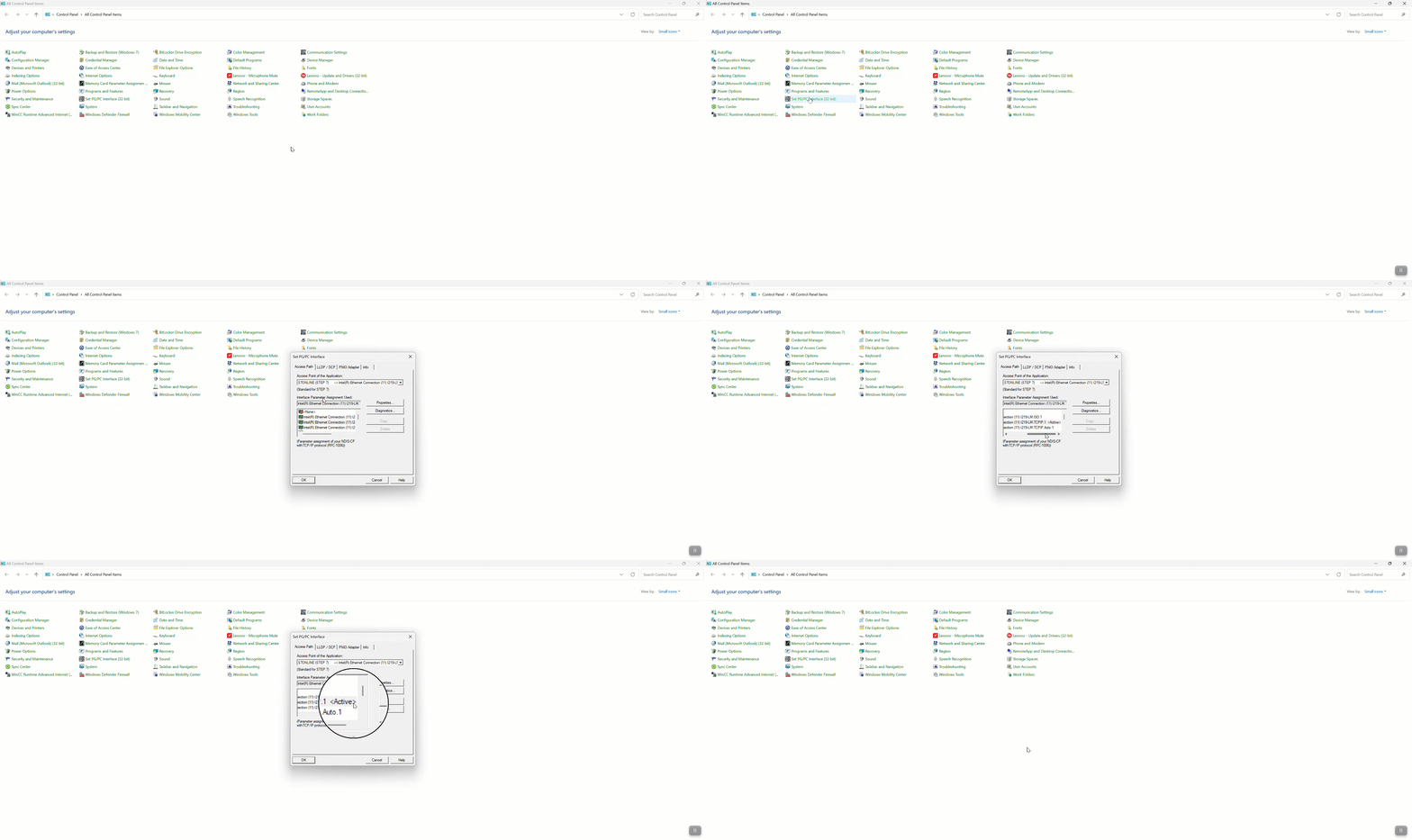
Before the HMI works inside TIA Portal with the project, you will have to change some settings inside control panel on your machine.
Go to “Control panel” on your machine.
Find “Set PG/PC Interface (32-bit)” and open it.
In “Access Point of the Application”, choose “S7ONLINE (STEP 7)”
In “Interface Parameter Assignment Used”, find “<your network adapter>.TCPIP.1” and highlight it.
Your network adapter could look slightly different depending on wifi or ethernet connection:
(e.g. “Intel (R) Ethernet connection (16) I219-V.TCPIP.1”)
Press “OK”
To check whether you saved the changes correct, you should be able to see the tag “<Active>” next to your network adapter inside the “Set PG/PC Interface”.
Robot setup
SRCI URCap Setup
For SRCI to work with your UR robot, you need to install the necessary URCap so the PLC is able to send commands to the robot.
Put the purchased URCap and activation file on a USB-stick, and insert it into the Teach Pendant or control box.
On the Teach Pendant, go to settings in the top-right corner.
In settings go to “System” → “URCaps” and press the “+” sign.
Find the USB-stick and open the URCap.
Restart the robot.
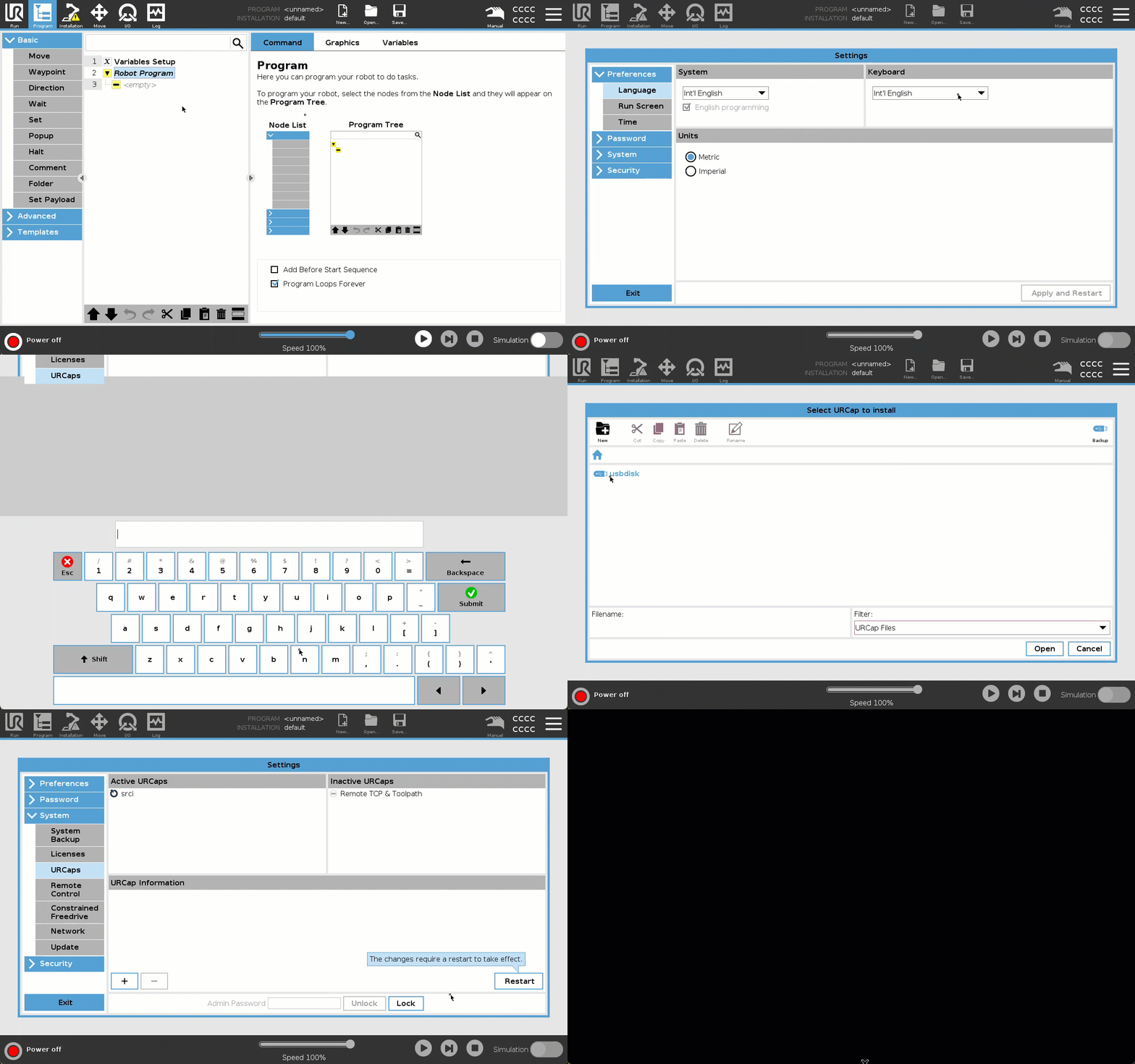
When the robot is booted, go to “Settings” → “System” → “URCaps” and find the inactive URCap and activate it with your activation file in the “+” sign.
Restart the robot for changes to take effect.
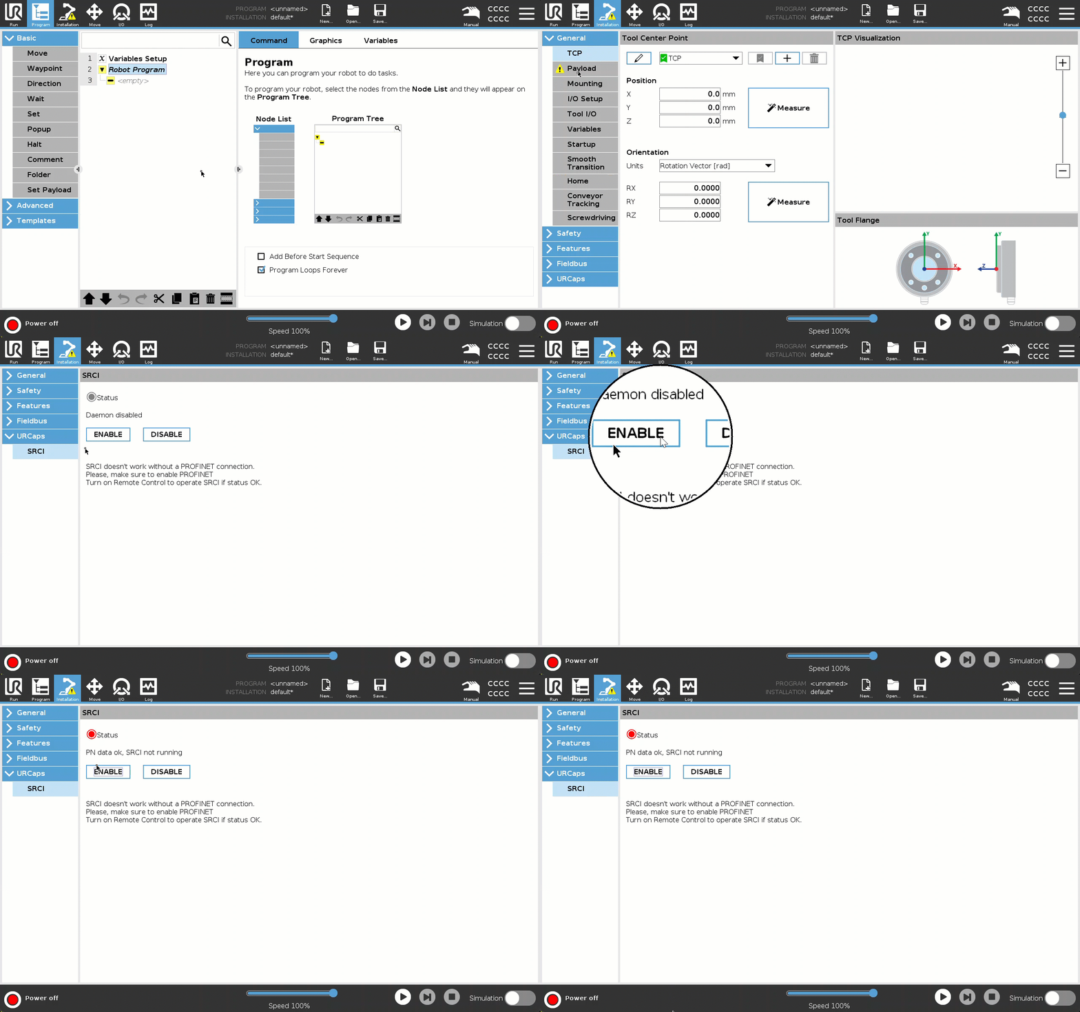
When the robot is booted, go to “Installation” → “URCaps” → “SRCI” and press “ENABLE”.
It is important to turn off the URCap after use, otherwise it will disable the robot automatically.
SRCI Robot program
Go to “Program” and insert a loop from the “Advanced” tab.
In the Loop, put in a Script from the “Advanced” tab.
In the Script, write:
interpreter_mode(True, True).Save the program with the name
srci.urp(case sensitive), and the installation with the namedefault.installation.During the enable sequence before powering on and brake releasing the cobot arm SRCI loads and executes this program. In essence, the program’s purpose is to suspend normal program execution by activating the Interpreter Mode, the interface used for interactive command execution during SRCI operation. Most often ‘srci.urp’ is a very simple program with only a single ‘interpreter_mode()’ script node but it may include any kind of initialization as long as it ends with activation of Interpreter Mode.
If other threads have to run in parallel to the program, make sure to end the thread with a
sync()Script command.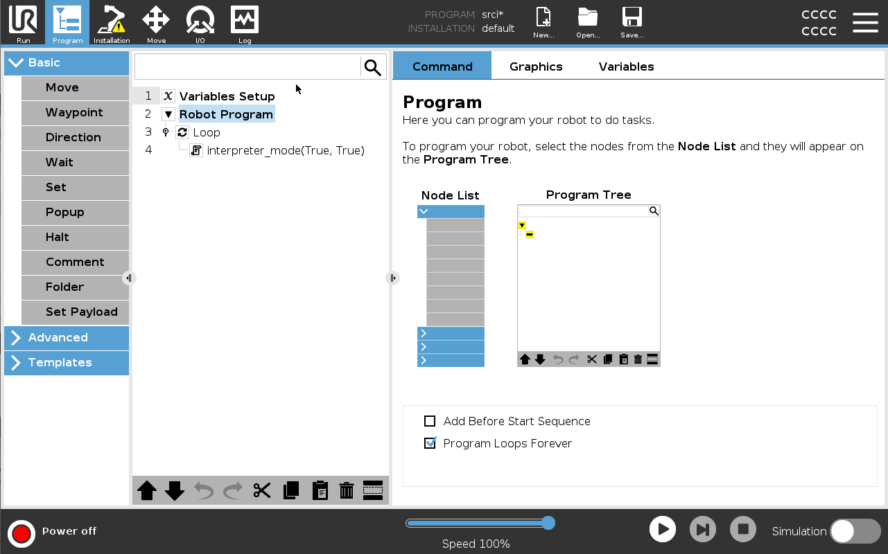
Enable PROFINET
The TIA Portal manages all PROFINET units on the network, and it is via the TIA Portal that you provision the PROFINET connection from the PLC to your cobot.
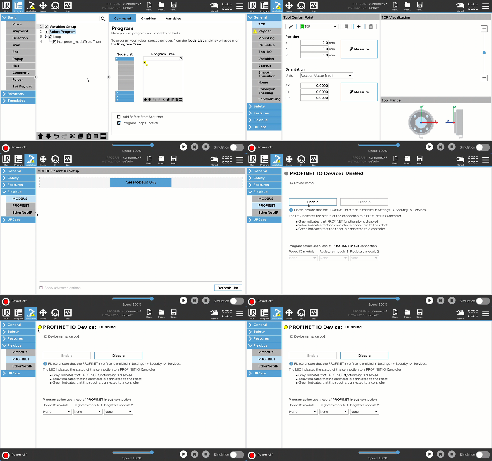
Go to “Installation” → “Fieldbus” → “PROFINET” → “ENABLE”.
The yellow LED indicates PROFINET is running on the robot, but PLC/IO controller is connected. The robot will be connected to the PLC via TIA portal in this step: TIA Portal robot setup.
Enable remote control
Your cobot is to be controlled by SRCI and no longer from the Teach Pendant. Therefore, it must be in Remote Control mode:
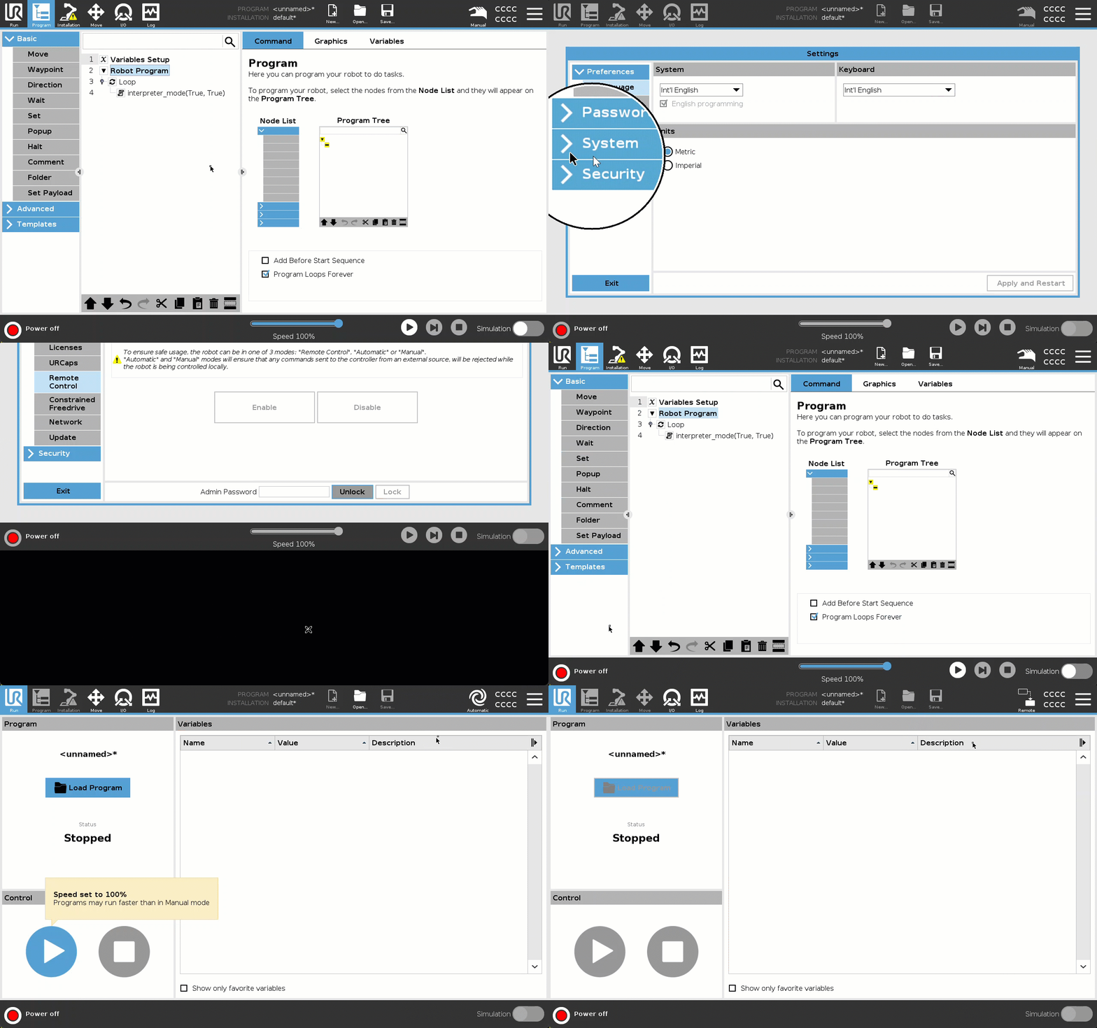
Go to “Settings” → “System” → “Remote Control” → “ENABLE”.
To enter remote control, your cobot has to be in “Automatic mode”.
TIA Portal robot setup
PROFINET robot setup
This step will show you how to configure PROFINET device name + IP address, in order to have the robot and PLC connected. Therefore, for this step to work, PROFINET has to be enabled on the robot.
If you know your robots MAC address/already have assigned a PROFINET device name to the cobot before, you can skip to step 6.
Find your robots MAC-address and enter the IP address.
Enter the terminal on the robot either with ssh if you know the IP address, or plug a keybord into the Teach Pendant and pressCTRL+ALT+F1.In the terminal, enter
ip addr showand find the robots MAC-address.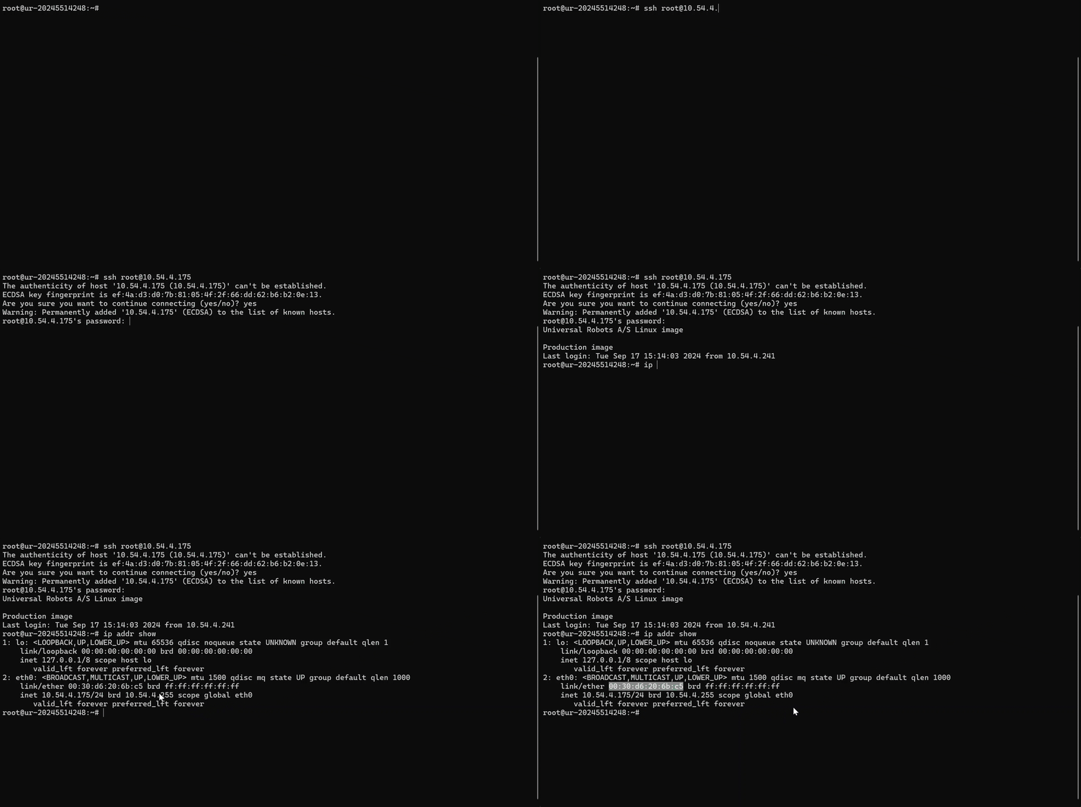
In TIA Portal, go to the project tree (left sidebar) → “Online access” → {Your network adapter} and press “Update accessible devices”.
Find “Accessible device [MAC-address of your robot]” and press “Online & diagnostics”.
Go to “Assign PROFINET device name” and enter a name you want for your robot.
In “Online & diagnostics”, go to “Assign IP address” and enter the IP address etc.
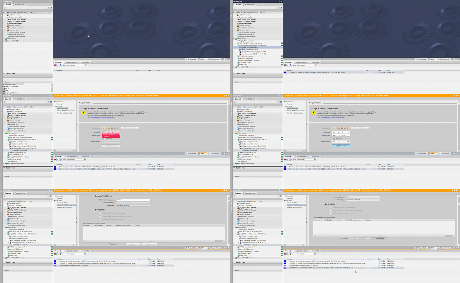
After assigning PROFINET device name and IP address, you can “Update accessible devices” in the project tree again and see the name has changed, and instead of the MAC address after the name, it should now be the IP address you just entered.
The device name should also be visible on on the robot in “Installation” → “Fieldbus” → “PROFINET”.
Add the PROFINET name and IP address to the robot in your network
Now that the robot has been configured, it still has to be configured in your network, in order for the PLC to find it.
Go to “Devices & networks” → right click your robot (URIODev1) → press “Properties” → “General” and enter the name you just configured on the robot.
Still in “Properties”, go to “PROFINET interface [X1]” → “Ethernet addresses” and add the robots IP address etc.
Still in “PROFINET interface [X1]”, go to “Advanced options” → “Real time settings” → “IO cycle” → click “Set update time manually” and change the update time to
32.000 ms.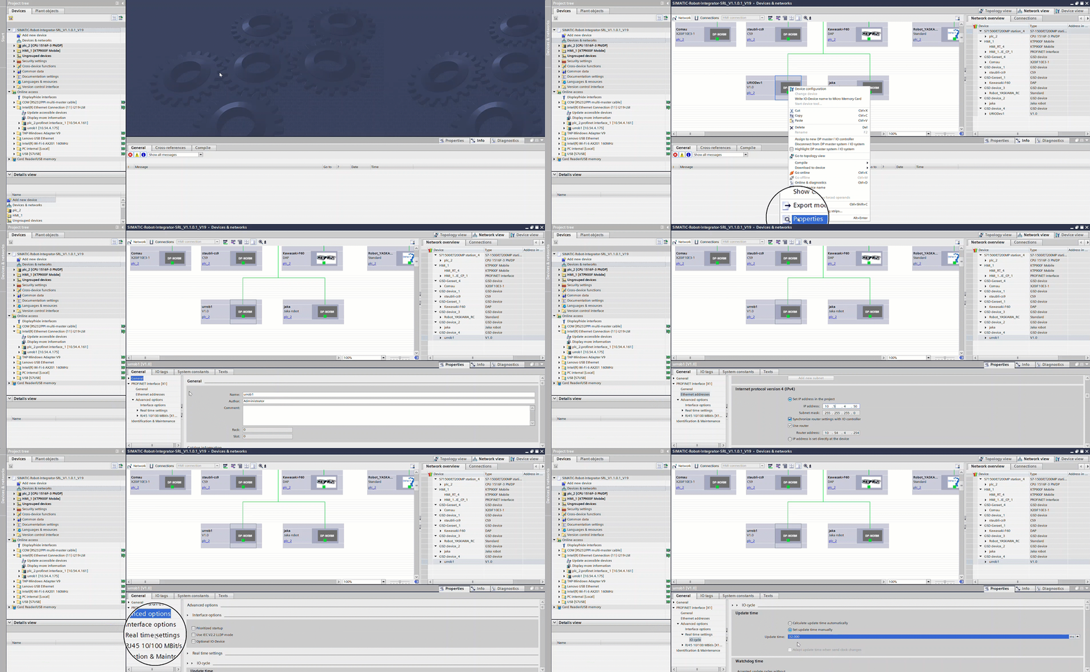
I/O Setup
SRCI works through the cobots I/O. Therfore you have to set up the correct I/O mappings:
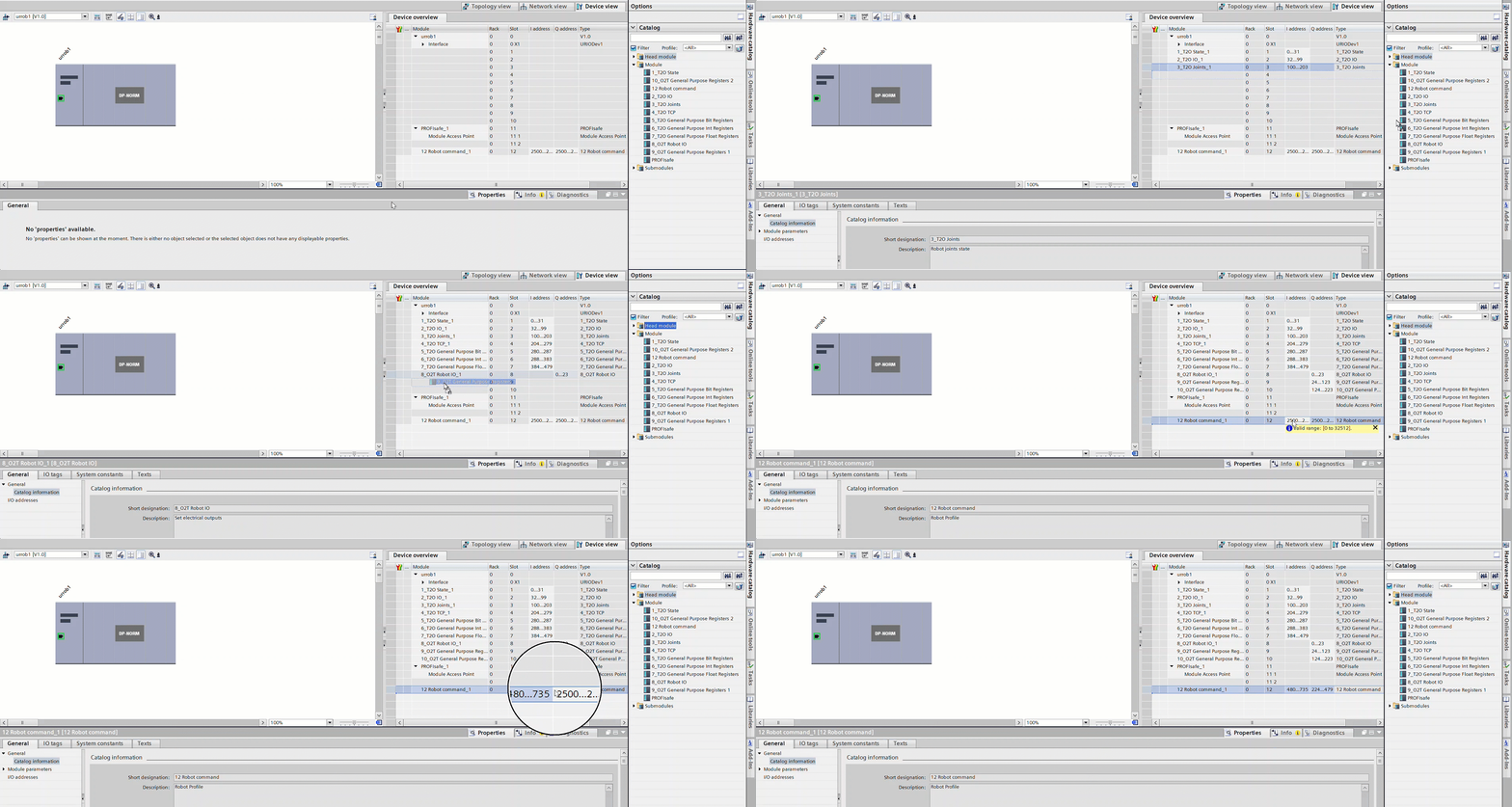
Go to “Devices & networks” → double click your robot, so you enter “Device overview” → go to the catalog (right sidebar) and expand “Module”.
Drag and drop the 10 missing modules into the device overview, so that the numbers in the names of the modules correspond to the slots of the robot.
It is important to insert these in the right order (1, 2, 3 etc.) so the I/O addresses align properly.
The I addresses should go from 0 to 735 acending from module 1 to 12, and the Q addresses should go from 0 to 479 from module 8 to 12.If the address %Q480 is already being used, please delete all the other robots in the project from your network
Download the UR datastruct
Go to the project tree → expand your PLC → expand “External source files” and press “Add new source file”.
Find and add the UR_datastruct, you just downloaded.
Right click the “UR_datastruct.udt” in “External source files” → press “Generate blocks from source”.
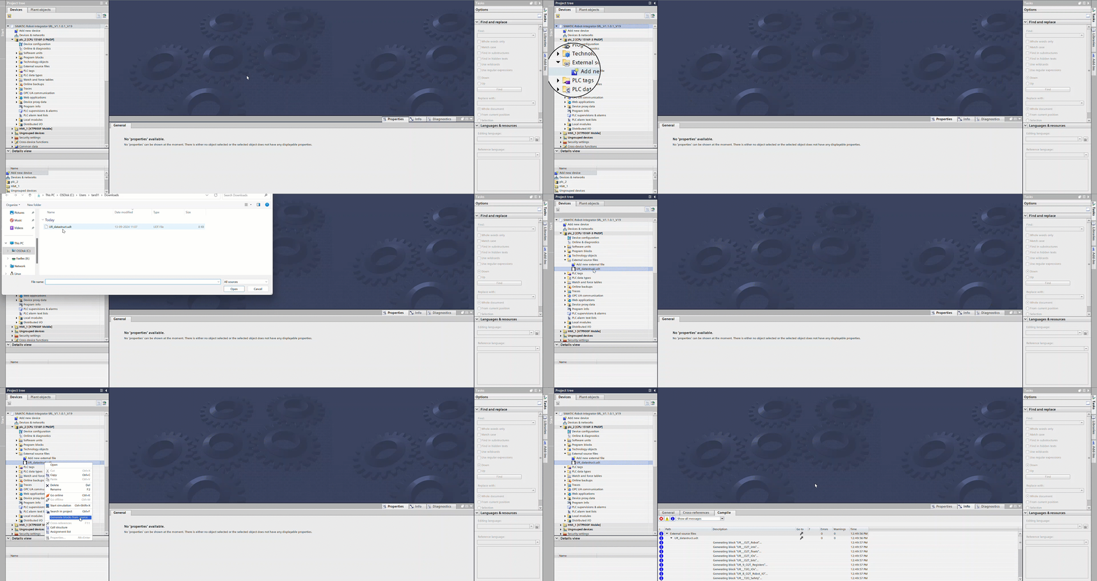
Now that the datastructure for the UR I/O has been added, and needs to be linked to the modules added before.
In the PLC tags or your own data block, make 2 tags:
URIof typeUR_T2Owith the first I address of module 1 (%I0.0if only 1 robot).This is the robots input data (Output from PLC) used for sending the robot data (Open/close gripper, safety, etc.)
UROof typeUR_O2Twith the first Q address of module 8 (%Q0.0if only 1 robot).This is the robots output data (Input to PLC) used for sending the PLC data (Gripper closed/opened, safety, etc.)

Configuration of project
Administrator password
Because you need Administrator privileges to program the robot, you need to change the Administrator password to your own.
In the TIA Portal project, search for “Administrator”
Under the HMI’s “User administration”, choose “Administrator” (Path: ..\Administrator\Name).
Double-click the password, and change it to your own.
Delete excess robots
In “Devices & networks”, delete all the robots you are not using.
Otherwise, the PLC will be looking for these on the network and cause an error, because it can’t find them.
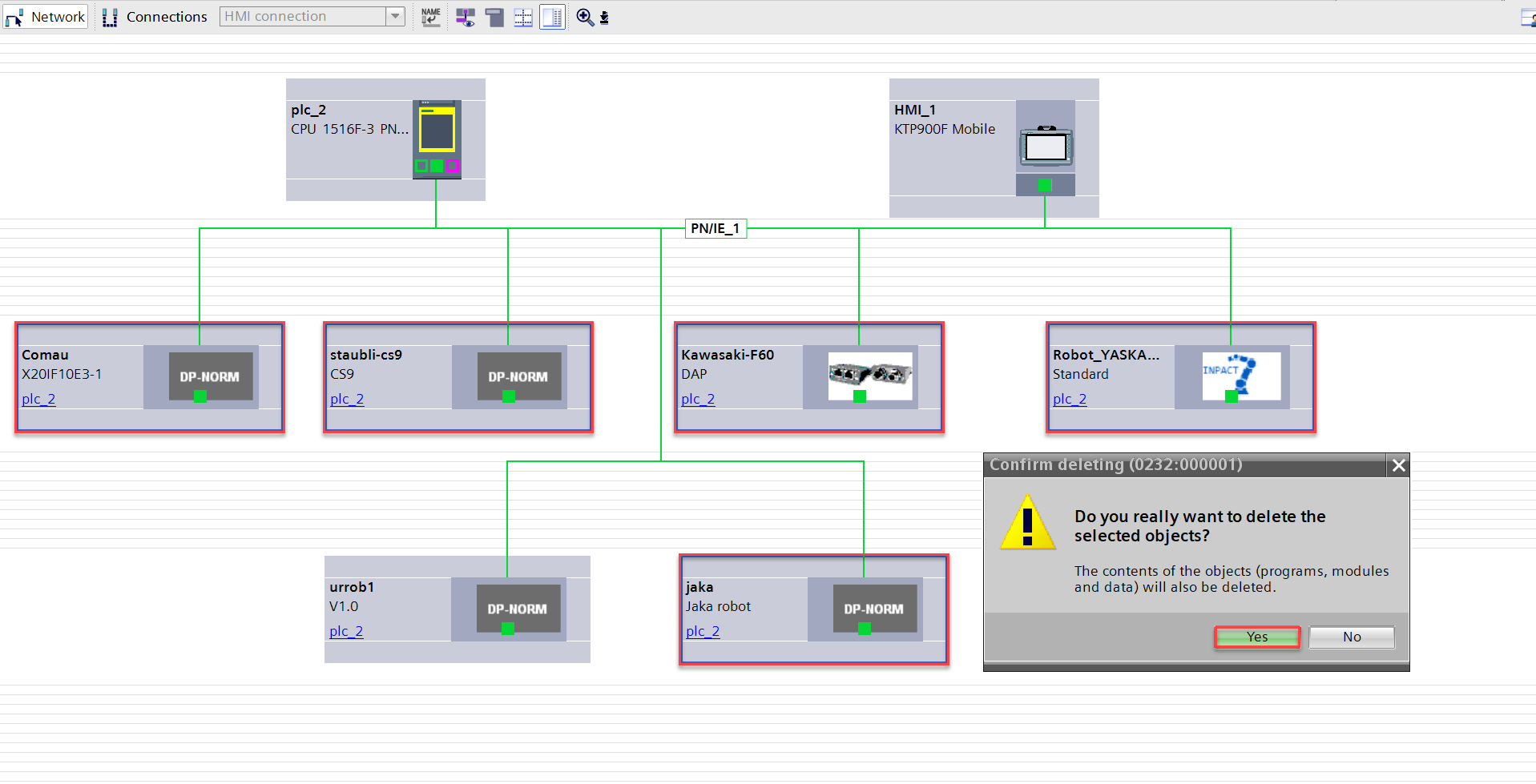
Go to “Program blocks” → “Robots” and delete the all robots you are not using.
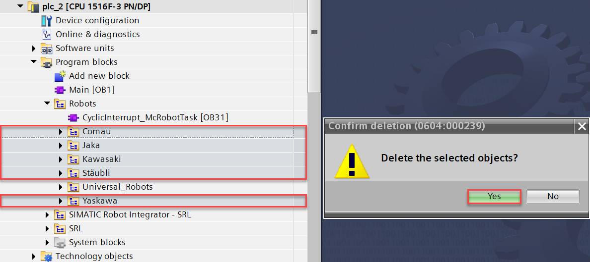
Now that the robots are deleted from the network and project, errors will occur, because these were referenced in other places of the project.
Go to “Program blocks” → “SIMATIC Robot Integrator - SRL” → “SiemensSRI” and delete the references in Network 1.
Still in “SiemensSRI”, also delete the other robot manufacturers networks, since these are also refering to the deleted robots.
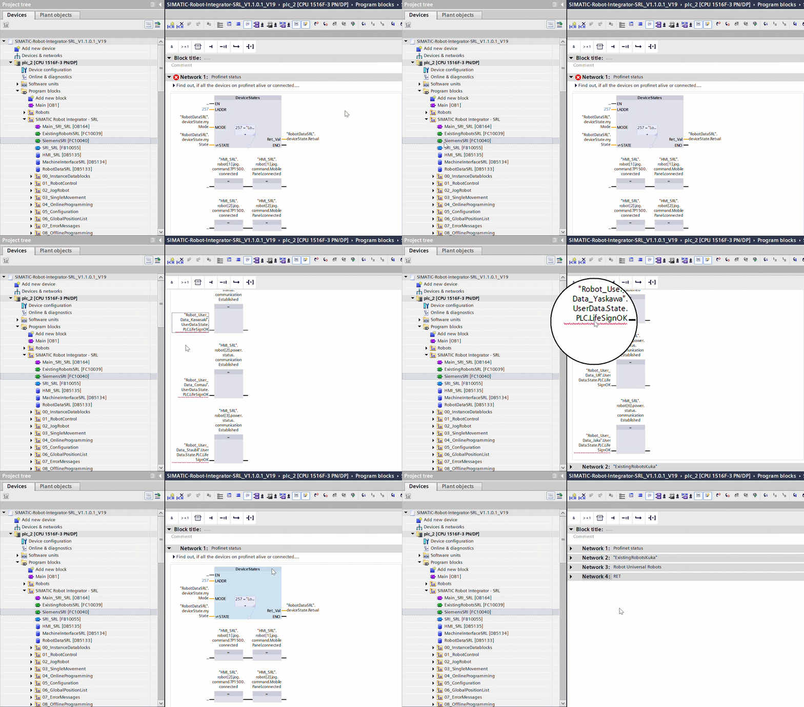
Lastly, go to “PLC tags” → “RobotCommunikation” and delete all the tags used for communicating with the deleted robots.

Adding more robots to the project
Now that unused robots are removed from project, it might be helpful to know how to add more robots if needed.
Remember: You need an SRCI license and URCap for each robot added to your project.
Go to “Devices & networks” → Catalog (right sidebar) → “Other field devices” → “PROFINET I/O” → “I/O” → “Universal Robots A/S” → “Collaborative robot”.
Drag & drop the “V1.0” device into your network to add a robot.
Follow the Robot setup and TIA Portal robot setup again, to set up the robot.
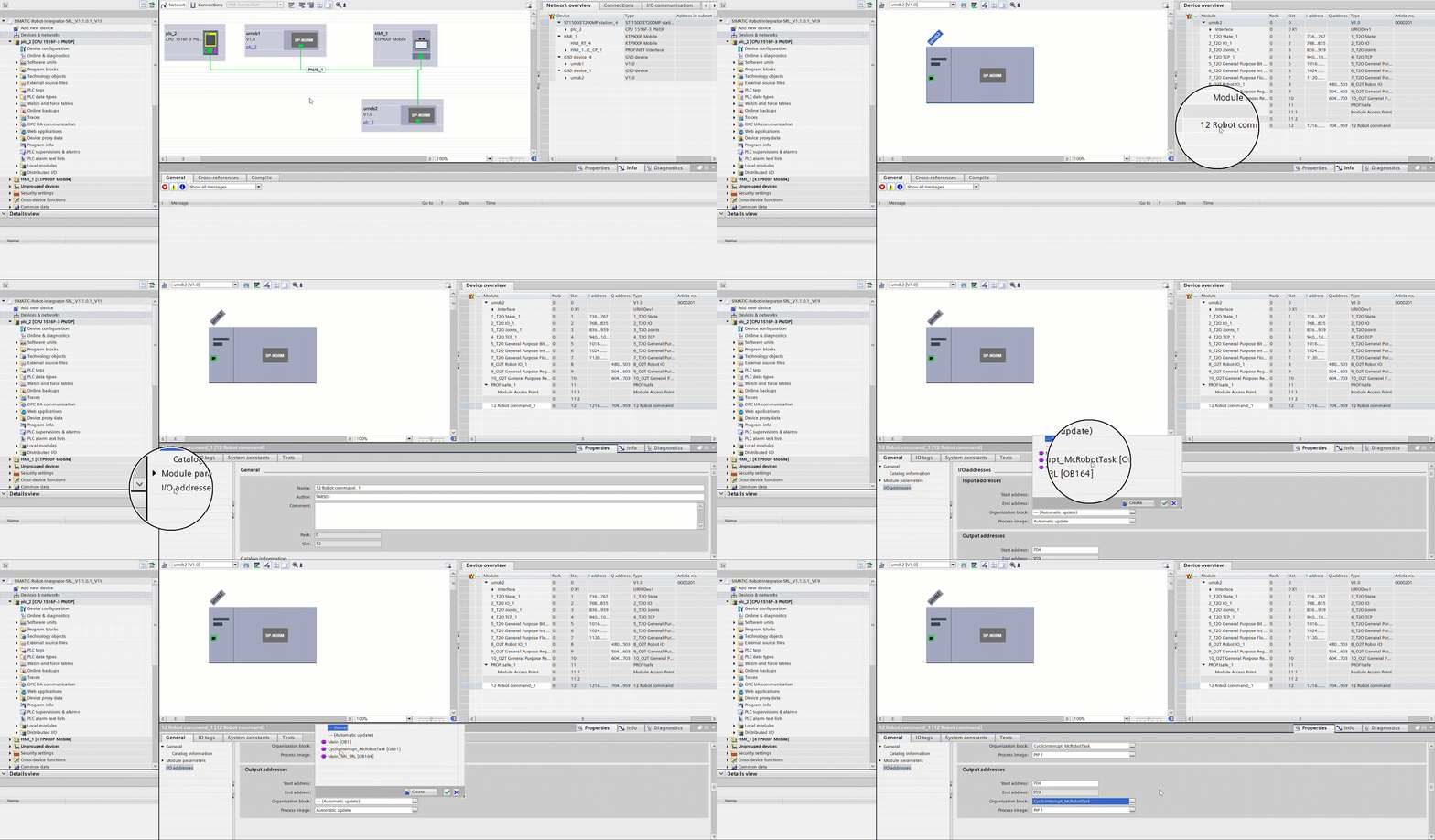
Make sure the robot’s I/O addresses are mapped to the right organization block:
In “Devices & networks”, click your new robot and enter “Device view”.
Click module 12 (“12 Robot command”) → “Properties” → “I/O addresses” and change the mapped organization block for the input AND output addresses to “CyclicInterrupt_McRobotTask”.
Make new DB’s and references to the robot:
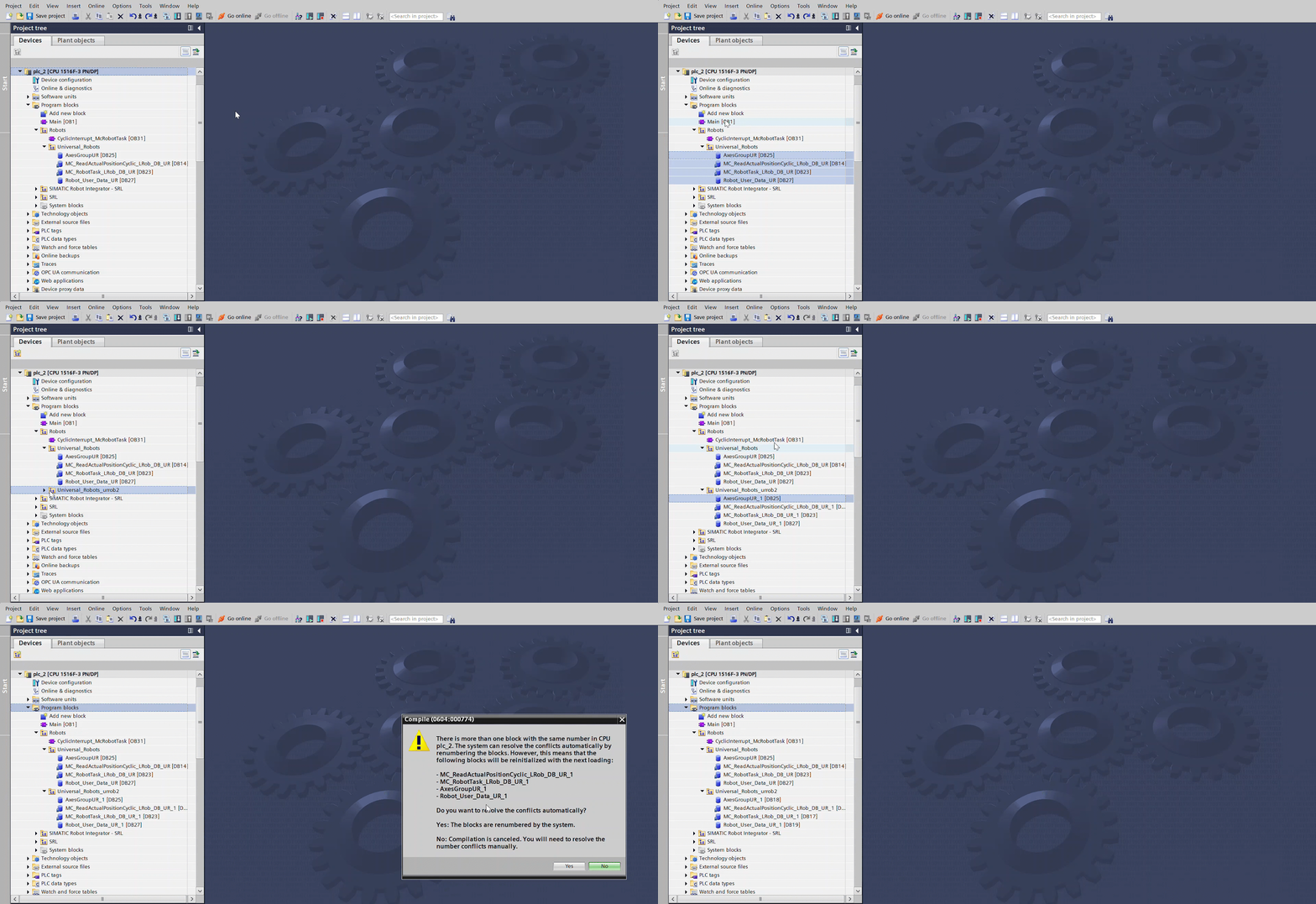
Go to “Program blocks” → “Robots” and make a new group for your robot (e.g. Universal_Robots_urrob2)
Copy the DB’s from “Universal Robots” into your new robot folder in “Robots”
Also change the names of the DB’s in both folders, so they are easily differentiable.
(E.g “AxesGroupURROB1” etc. and “AxesGroupURROB2” etc.)
Right click “Program blocks” → “Compile” → “Software (rebuild all)”.
By doing this, TIA Portal will automatically renumber the new DB’s, so they are not referenced as the other robots DB’s.
Integrate the new robot in the project:
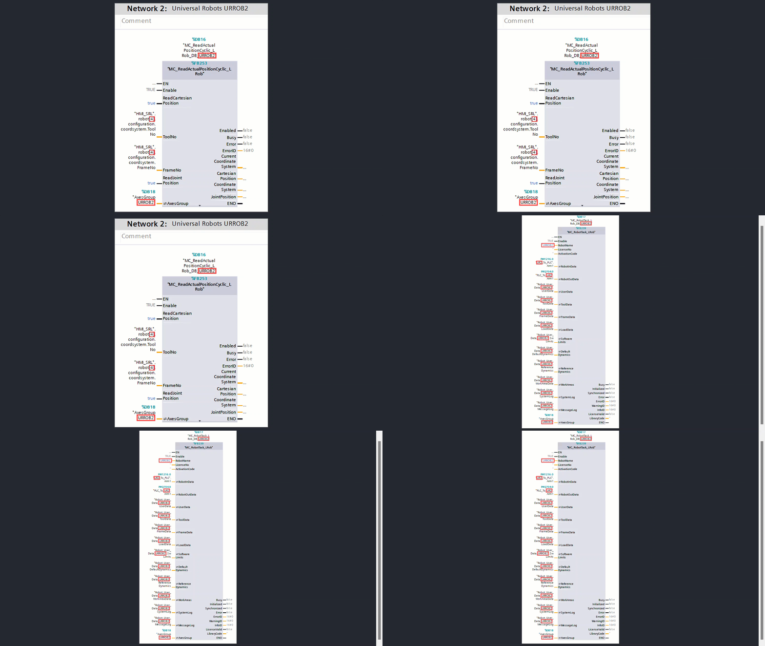
Go to “Program blocks” → “CyclicInterrupt_McRobotTask [OB31]” and copy the Universal Robots network.
Paste the network → Rename the networks to fit the 2 robots → Change the references in the new networks, to fit the DB’s of the new robot instead of the old (“MC_RobotTask_LRob_DB_URROB1” → “MC_RobotTask_LRob_DB_URROB2”).
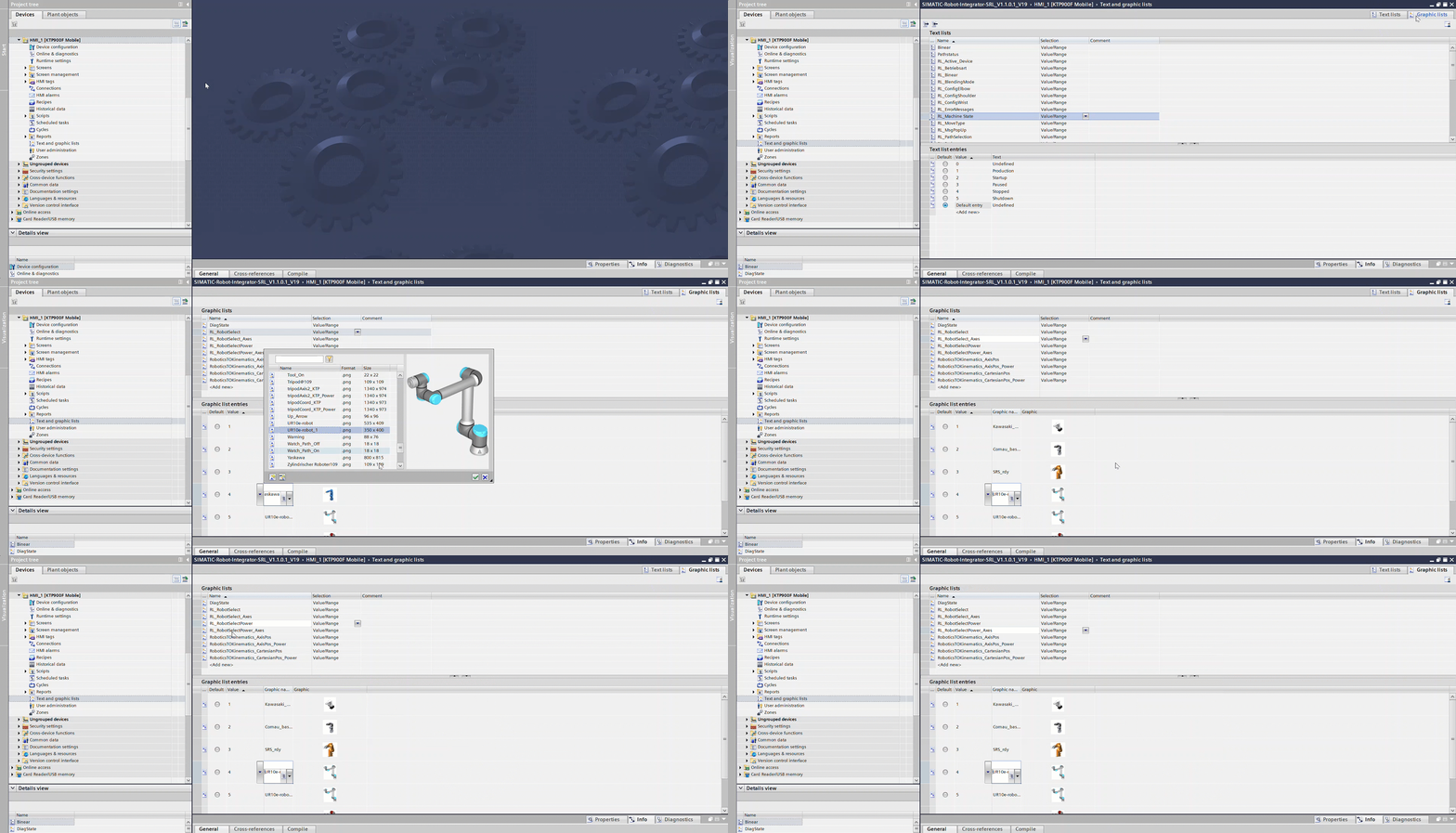
Change the robot pictures in the HMI, to match the new robot:
Go to the HMI in the project tree → double-click “Text and graphics lists” → Open “Graphics lists” → change the respective robot’s picture in the 4 list “RL_RobotSelect”, “RL_RobotSelect_Axes”, “RL_RobotSelectPower” and “RL_RobotSelectPower_Axes”.
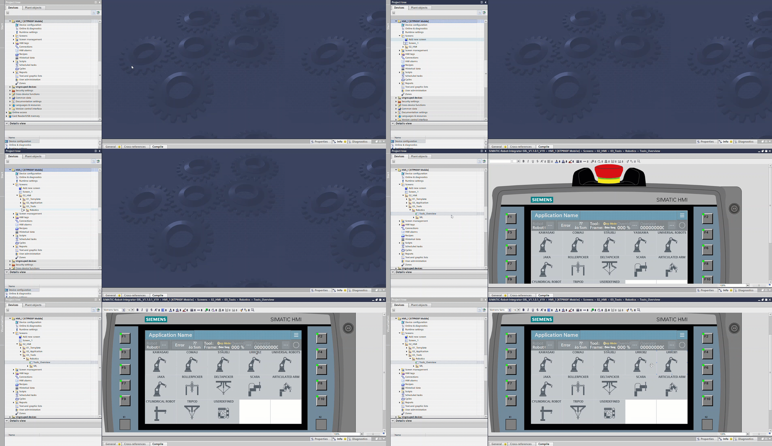
Change the name on the screen on the HMI to match with the new robot:
In the HMI in the project tree, go to “Screens” → “02_HMI” → “03_Tools” → “Robotics” → open the “Tools_Overview” screen and change the name of the new robot.
Avoid error when connecting to robot:
In the PLC in the project tree, go to “Program blocks” → “Robots” → <Your new robot> → “Robot_User_Data_…” DB.
In the DB, go to “UserData” → “Config” → “RC” and set
WaitAtBlendingZone = True.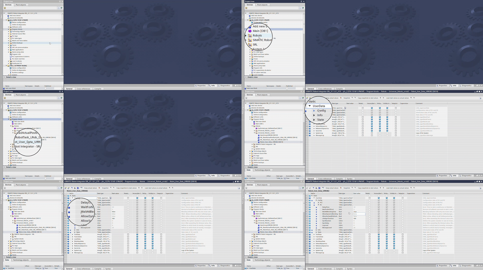
FAQ
How to set payload and tools?
The payload is configured by first specifying the data for the load to be picked, followed by the data for the tool that will perform the pick:
In the cyclic organization block (main), add the “MC_WriteLoadData_LRob” FB:
The “WriteLoadData” function takes the
LRob_typeRobotLoadDatadata type as argument, containing all neccessary information about the payload (Mass, CoG, inertia), just like setting up payload in the installation on the robot.In this example, a DB has been made with neccessary values, called “Robot_control”. This DB contains the
LRob_typeRobotLoadDatadata type, execute bit, error bit, error id etc.
Information about “ProcessingMode” and “SequenceFlag” can be found in the SRCI manual.
Tip
A good idea is to set up a switch that resets the execute bit for the FB.
If you do this, it’s easier to check whether the bit hangs (doesn’t reset properly) because it couldn’t execute as a result of errors:
Note
LoadData is not used directly robot on it’s own. This is because Positions in SRCI are defined with a Tool as an argument, that in turn references LoadData. In order to see the effect of the “WriteLoadData” FB, it is necessary to setup the “WriteToolData” FB, because it uses the above configured LoadData as an argument.
Just like above add the “MC_WriteToolData_LRob” in the cyclic OB:
The “WriteToolData” function takes the
LRob_typeRobotToolDatadata type as argument, containing all neccessary information about the Tool (TCP) (XYZ-Position, RxRyRz-Orientation), just like setting up Tool in the installation on the robot.

Tip
It is again recommended to set up a swich for the execute bit like mentioned in step 2 above.
Set up the proper values about payload and tool in the data types in the DB:
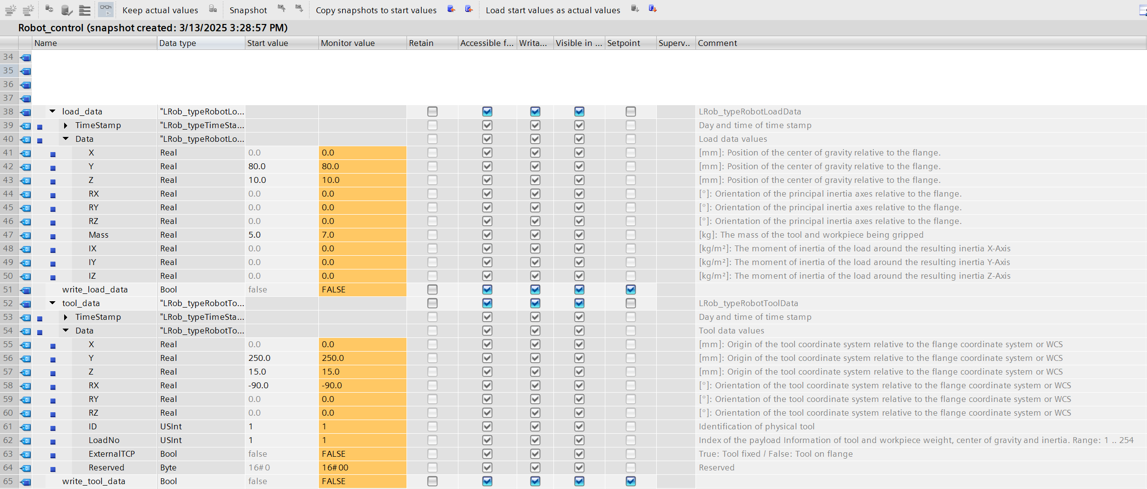
Write the load data to a Load index on the robot (1 ..254).
Write the tool data to a Tool frame index on the robot (1 ..254)
Now it is possible to write load data to a tool!
Just remeber to reference the tools when defining a Position.