You're reading the documentation for an obsolete version. For the latest released version, please have a look at mp1.5.
Moving the Robot Using Frames
Brief: In this example, we show how to use the movel command with frames in two different ways: 1) using a frame itself as a goal pose in movel, and 2) moving to a goal pose defined relative to a frame. We also illustrate how a motion trajectory can be implemented using attached frames and then easily adjusted in space by moving their parent frame without having to recalculate the goal poses of individual motions.
New and newly modified URScript functions used in this example:
[movel()](../worldmodel-urscript-intro.md#movel - new behavior)
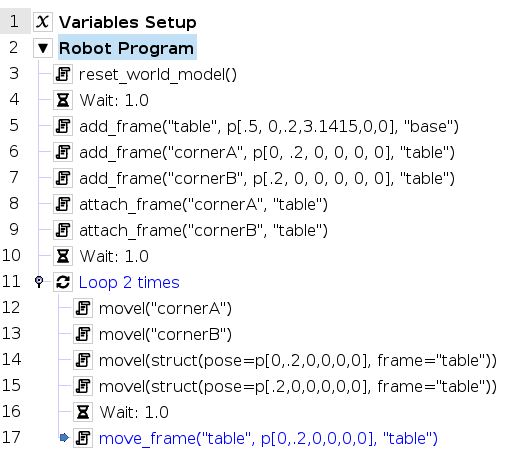
The example program adds three frames to the world: “table” that represents the reference frame of a table, and two corner frames, “cornerA” and “cornerB” that represent two corners of a table. It attaches “cornerA” and “cornerB” to the “table” frame and then demonstrates using a movel command to move back and forth between “cornerA” and “cornerB” using the two different usages of movel. After moving back and forth between “cornerA” and “cornerB” twice, it moves the “table” frame and demonstrates how the corners move with the “table” frame. It then moves back and forth between the corners. This illustrates how a motion trajectory can be implemented using attached frames and then easily adjusted in space by moving their parent frame without having to recalculate the goal poses of individual motions.
Program |
Demonstration |
|---|---|
|
|
Let’s go through the some highlights of this example in greater detail:
Resetting the World Model
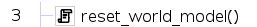
This removes any frames that have been added to the world. It’s useful when the program is set to loop forever, otherwise, the calls to add_frame() later in the program attempt to add frames with the same name that already exists. This throws an error.
Adding and Attaching Frames
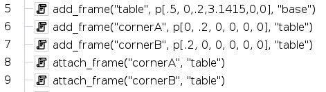
This adds a frame “table” relative to the robot’s “base” frame and then the corner’s of the table, “cornerA” and “cornerB” relative to the table frame. It then attaches the corners to the table frame.
Moving to the Corners
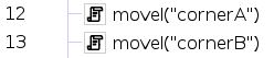
This commands the robot to complete two movel motions to “cornerA” and “cornerB”. The movel command automatically computes the poses of “cornerA” and “cornerB” in the world by analyzing how they are attached in the kinematic tree.
Moving Relative to “table”
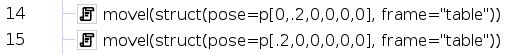
This commands the robot to complete two movel commands to specified poses expressed in the “table” frame. The poses in the “table” frame match the placements of “cornerA” and “cornerB” so the robot appears to move to “cornerA” when completing line 14 and to “cornerB” when completing line 15.
Moving the Robot Relative to the TCP
Brief: In this example, we show how to use the movel command with frames to follow trajectories that are defined relative to the robot’s TCP. It shows a comparison of how the trajectory can be performed using pose_trans vs using movel with a struct argument.
New and newly modified URScript functions used in this example:
[movel()](../worldmodel-urscript-intro.md#movel - new behavior)
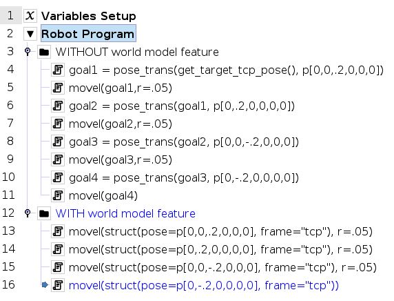
The example program shows how to make the robot follow a trajectory defined in the TCP frame using two different approaches. The first subprogram shows how get the TCP pose before the trajectory starts and then use pose_trans to manually place each the TCP pose of each waypoint relative to the TCP pose of the last waypoint. The second subprogram demonstrates how to use the new struct-argument feature of movel to define the goal pose explicitly in the TCP frame for each motion.
Program |
Demonstration |
|---|---|
|
|
Let’s go through the some highlights of this example in greater detail:
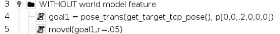
Using pose_trans to plan relative waypoints:
 **
**
This uses get_target_tcp_pose() to obtain the current TCP pose and then shifts it by 0.2m in the TCP’s zdirection using pose_trans() to get the first goal.
 **
**
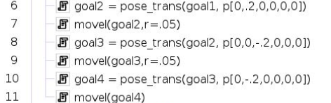
The remaining waypoint goals are shifted from previous goal TCP poses also using pose_trans(). The “goal2” pose is shifted by 0.2m in the y direction of the “goal1” pose. The “goal3” pose is shifted -0.2m in the z direction of the “goal2” pose… and so on.
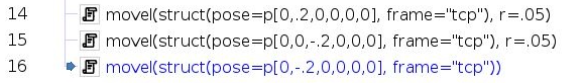
Using the struct feature of movel:
 **
**
The members stored in the struct are the “pose” and the “frame” in which the pose is represented in. In this case, the “pose” and “frame” members indicates that the desired robot motion is 0.2m in the zdirection of the “tcp” frame. The goal waypoint is resolved before the motion starts by computing the goal pose using the TCP frame BEFORE the motion begins.
 **
**
The remaining TCP goals are computed in the same manner. Note that the pose of the TCP frame is used to compute the goal for each movel for the movel motion starts.