You're reading the documentation for an obsolete version. For the latest released version, please have a look at mp1.5.
Introduction
Terminology & Background
Coordinate Frame
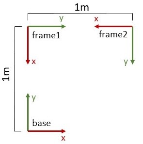
Coordinate frame is another word for Cartesian coordinate system. We often use the word frame as an abbreviation*.* A coordinate frame consists of a three-dimensional origin in space along with three mutually perpendicular coordinate axes. The coordinate axes are labelled as x, y, and z and are mutually perpendicular according to the “right-hand rule” In the example diagram on the right, there are three coordinate frames depicted with names “base”, “frame1” and “frame2”. The x and y axes are all shown and labelled but the z axes point out of the page and are not shown.
Pose
A pose is the unique numeric representation of a position and orientation in space defined in a specific coordinate frame. Coordinate frames have poses. In the diagram on the right, for example, the pose of coordinate frame *”*frame1” in the coordinates of coordinate frame “base” are (0m, 1m, 0m, 0rad, 0rad, -pi/2rad). (The orientation is expressed in rotation vector form, where the vector direction and magnitude specify the rotation direction and amount of rotation respectively. See here for more info.) This means that “frame1” can be measured to be 1m in the “base” y axis, and is rotated by -pi/2 radians around the “base” z axis.
More examples from the diagram at right:
the pose of “base” in the coordinates of “frame1” is (1m, 0m, 0m, 0rad, 0rad, pi/2rad)
the pose of “frame2” in the coordinates of “base” is (1m, 1m, 0m, 0rad, 0rad, pi rad)
the pose of “frame1” in the coordinates of “frame2” is (1m, 0m, 0m, 0rad, 0rad, -pi/2rad)
Reference Coordinate Frame
All poses are defined in a specific coordinate frame. We call this coordinate frame the reference coordinate frame or just reference frame for short. When no reference frame is explicitly mentioned, it’s implied that the reference frame is the robot’s base coordinate frame.
As an example, the poses of the frames in the diagram at right in the “base” reference frame are:
“frame1” pose is (0m, 1m, 0m, 0rad, 0rad, -pi/2rad)
“frame2” pose is (1m, 1m, 0m, 0rad, 0rad, pi rad)
“base” pose is (0m, 0m, 0m, 0rad, 0rad, 0rad)
Notice how the pose of frame “base” in the reference frame “base” is (0m, 0m, 0m, 0rad, 0rad, 0rad). This is always the case when expressing the pose of a frame expressed in the coordinates of itself
Overview of What’s New
As of Polyscope 5.16.0, URScript programmers will be able to interact with coordinate frames as objects. The concept of coordinate frames isn’t new and would be well known to any URScript programmer with a background in robotics. Much of the new functionality that we’ve implemented could have been accomplished by a knowledgeable roboticist along with use of pose_trans, pose_inv, etc. We’ve tried to make it easier for less knowledgeable programmers to accomplish the things that more experienced roboticists can do. As for the more experienced roboticists, we’ve tried to make it so their URScript programs can be simpler, easier to read, and more maintainable (reduce the use of pose_trans, pose_inv, etc.)
Here’s a high-level overview of what’s new (more details and examples are in the sections that follow):
Coordinate Frames as Objects
We have added the concept of a coordinate frame as an object in the URScript language. Coordinate frames can be:
given unique names like “frame1” or “table corner”
referred to by their name in many existing motion commands (e.g., movel, movep, movec, etc)
added and removed while a program is running
attached and detached from one another
moved around
assigned inertial properties (e.g., mass and inertia)
Programs Don’t Have to be Robot-centric
There are three “special” frames that always exist in a URScript program
“world” is the only truly stationary frame. It cannot be moved or attached to any other frame.
“base” corresponds to the robot’s base frame. It is always attached to the “world” frame and can be moved around.
“flange” corresponds to the robot tool flange. It’s always attached to the “base” frame and moves when the robot’s joints move.
“tcp” corresponds to the tool-center point and matches up with the existing TCP concept in URScript. It is placed relative to the flange using the existing set_tcp command. It’s always attached to the “flange” frame.
Traditionally, URScript programs have been mostly robot centric, meaning that all the motion commands (movel, etc.) take goal poses expressed in the robot frame. The consequence of this is that if the robot’s base moves in space, the goal poses being passed to the motion commands must be updated to account for the robot’s base motion. Most of the builtin URScript commands have been expanded in capability to accept 1) the name of a coordinate frame as a goal, and 2) a pose expressed in a specified frame as a goal. For example, if a program has a frame called “frame1”, a call to movel(“frame1”) would command the robot to move the tcp’s pose to match the pose of “frame1” in the world frame. The controller does the math so that the programmer does not need to always specify goal poses to the motion commands in the robot frame.
Backwards Compatibility: we have only added new capabilities to the motion commands. All existing ways of using the motion commands work fully and are unchanged so URScript programs that are working now without using these new features will continue to work just as they always have.
Relevant Examples:
Moving the Robot Relative to the TCP
Manipulating the Kinematic Tree
Being able to attach and detach coordinate frames lets programmers create trees of attached frames. We call these kinematic trees. To be as precise as possible, the controller only knows one kinematic tree with the “world” frame at its root. When programmers attach frames to each other, they aren’t creating new kinematic trees, they are manipulating sub-trees of the controller’s kinematic tree. Here are some basic properties:
The “world” frame is the root of the kinematic tree.
The “flange” is always attached to the robot “base” frame so that the it moves both if the robot’s joints move but also if the robot’s “base” frames moves.
The “tcp” is always attached to the “flange” frame.
The robot “base” frame is always attached to the “world” frame but it can be moved.
Moving a frame also moves its attached children frames in the same way.
New frames that a programmer adds are attached to the “world” frame by default until they are attached elsewhere.
New frames can be attached to any existing frame including the “flange”, “tcp” and the robot’s “base” frame.
Frames that are attached to the “flange” frame also move when the robot’s joints move.
Relevant Examples:
Payload Computation
Frames can be assigned inertial properties which can be used to compute the robot’s payload when they are attached to the robot’s TCP frame. This could be useful for pick-and-place tasks when the object inertial properties are known. In this case, the inertial properties of the pickup tool (gripper or suction cup) could be assigned to the “tcp” frame and a frame could be placed that represents the part being picked also with inertial properties assigned. When the part frame is attached to the “flange” or “tcp” frames, the inertial properties of the combined masses and inertias can be automatically computed and set as the total robot payload.
Backwards Compatibility: we have only added new capabilities and existing URScript payload commands remain unchanged.
Relevant Examples:
Motion in a Moving Frame
We created a new feature called “frame tracking”. It’s built on top of the existing “path offset” feature and lets users specify the world model frame that a robot trajectory should be performed in. The “frame tracker” updates the robot’s motion to follow the trajectory in the tracked frame even while the frame moves in time, provided the frame’s motion is smooth and continuous. To use this feature, the programmer adds a frame to the kinematic tree, enables frame tracking on the frame, and then moves the frame with the move_frame() command.
Here are some interesting facts:
Frame tracking is a key part of MotionPlus’s coordinated motion feature (see here) for welding, where the robot is commanded to follow a weld trajectory defined in the moving frame of an external axis positioner.
The frame tracker naturally handles motion of the robot base without any additional input from the user. This would be useful if the robot is mounted on a rail.
Relevant Examples: