PROFINET on Polyscope 5
Note
This guide was tested on Polyscope X 5.26.0 and Siemens TIA Portal V19.
Some images are very detailed. To see the full image, right-click and open in a new tab.
Setup
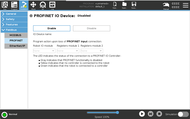
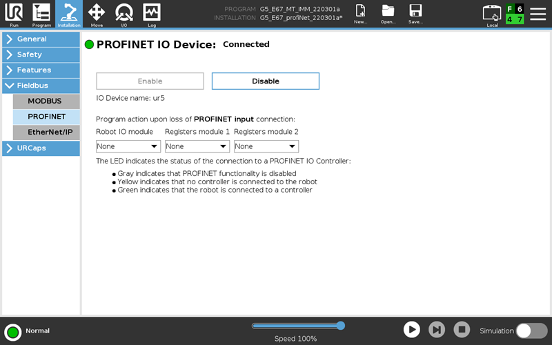
1. ROBOT: Tap the Installation tab and, under Fieldbus, select “PROFINET”. Tap “Enable”.
Save the installation for the changes to take effect the next time the installation is loaded.
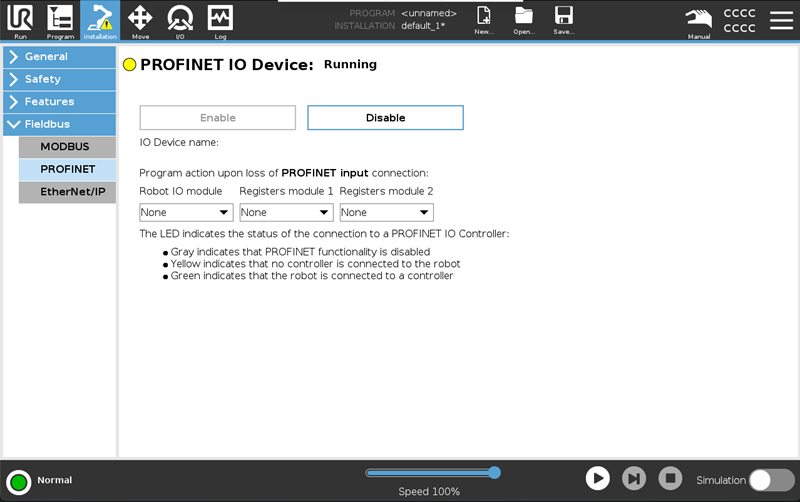
2. ROBOT: The yellow LED indicates PROFINET is running on the robot. No PLC/IO controller is connected to the robot.
3. Add Universal Robots GSD file:
Download GSDML file:
For software versions 5.25 and earlier GSDML-V2.42-UR-PROFIsafe-20220517.xml.zip
For software versions 5.26 and later GSDML-V2.45-UR-PROFIsafe-20251201.xml.zip
Unzip the GSDML file.
In the title bar in TIA Portal, go to “Options” → “Manage general station description files (GSD)”.
Browse for the folder with the GSD file in.
Select the GSD file and install it.
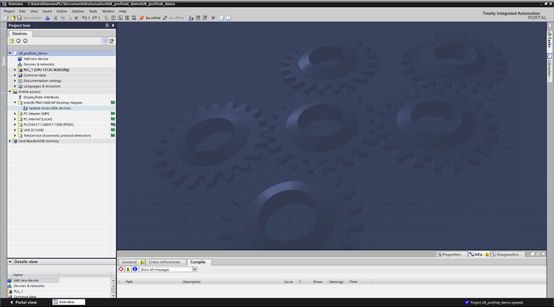
4. PLC: Open a project in Siemens TIA Portal.
In the Project Tree of the Project view, navigate to: “Online access → {your network adapter}”.
Click “Update accessible devices”.
5. PLC: Identify the robot and the PLC you want to connect. Assign IP addresses and names to the equipment.
Expand the desired accessible device and double-click “Online & diagnostics”.
In the device’s diagnostics page, expand Functions and click “Assign IP address”.
Enter the desired IP address and subnet mask, and tap “Assign IP address”.
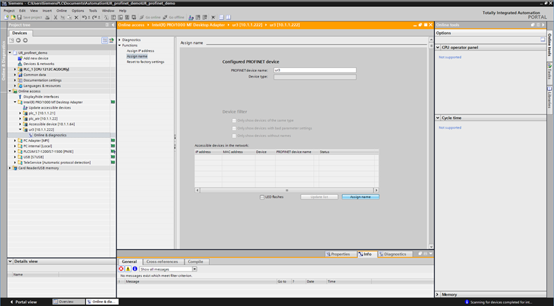
Still in the diagnostics page click “Assign name”.
Set the PROFINET device name and click “Assign name”.
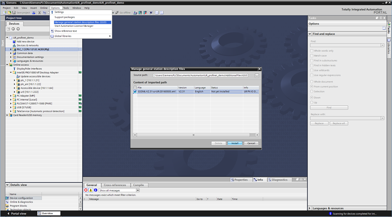
6. PLC: Import the Universal Robots’ GSD file.
Navigate to “Options → Manage general station description files (GSD)”.
Select to the right GSD and install.
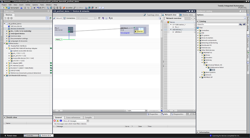
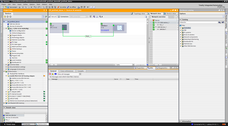
7. PLC: In the top of the project tree access Devices & networks.
Locate the UR I/O device in the catalog path: “Other field devices→PROFINET IO→I/O→Universal Robots A/S→Collaborative Robot→V1.0”
Drag-and-drop it into the network view and connect the PLC and the I/O device by dragging a line between their (green) PN/IE ports.
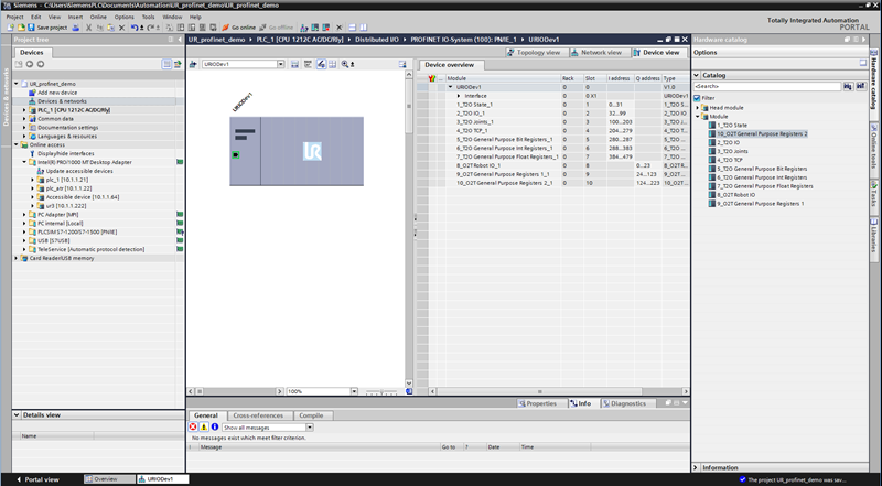
8. PLC: Double-click the I/O device in the Network view.
All modules are pluggable, and are named according to their corresponding slot numbers.
Each module can be drag-and-dropped from the “Catalog→Module” to the empty fields in the Device overview.
In this example all modules are plugged in. Notice how the input addresses (I) and output addresses (Q) are assigned, since you will need these to access the data.
9. PLC: Double-click the I/O device in the Device view to get the module description.
In the General tab select “Ethernet addresses”, and select “Use IP protocol”.
Set the same IP address as those assigned to the online device.
Deselect “Generate PROFINET device name automatically” and type in the same PROFINET device name as the one assigned to the online device.
10. PLC: This step requires PLC firmware version 3.0 or higher.
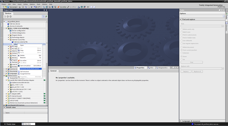
Navigate to “External source files”.
In the project tree, double-click “Add new external file” to open the file “UR_datastruct.udt”.
Import the user-defined data types by right clicking the newly added external source file and select “Generate blocks from source”.
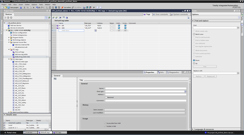
In the PLC tags (or your own Data Block), create tags corresponding to the modules you have enabled. Make sure the input addresses (I) and output addresses (Q) of the tags match those of the modules.
If all modules are enabled and placed in order in the IO memory, create a single PLC input tag of the data type: UR_T2O and a single PLC output tag of the data type: UR_O2T to map all data.
Both are visible in “PLC data types” in the project tree.
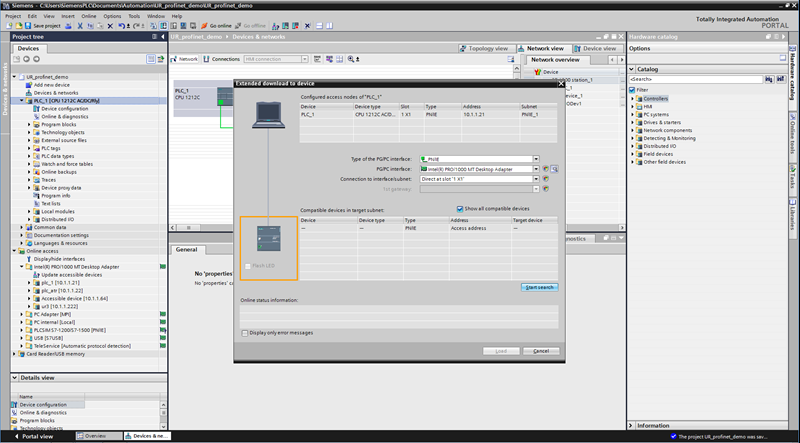
11. PLC: Download the program to the PLC.
In the menu bar click the download icon and tap “Start search” in the download dialog.
Select the PLC and click “Load”.
12. PLC: Confirm all blocks, tags and modules in the project tree are green.
13. ROBOT: Confirm the LED in the Installation tab is green.
14. PLC: In the project tree, navigate to your tag table (or Data Block) and expand your input tag to inspect values sent from the robot.
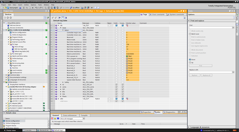
Everything is now configured!
More information
More information about the PROFINET can be found on the Polyscope 5 support site
More information about PROFIsafe can be found in Profisafe guide