4. Layout Creation
4.1. Catalog Panel
Open the Catalog panel
Navigate through the available categories
Select items and modify properties such as name or size
You can add components such as robot stands, conveyors, pallets, vacuum tools, accessories, end-of-arm tools, and workpieces
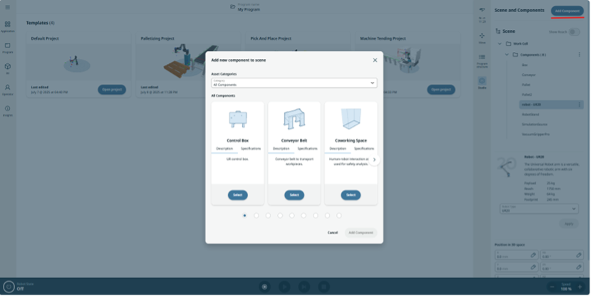
Catalog Panel
4.2. Work Cell Accessories
4.2.1. Robot Stand
The robot stand enables users to adjust the robot’s Z-axis position in the scene with a configurable height.
Properties
Position in 3D Space
Configurable height
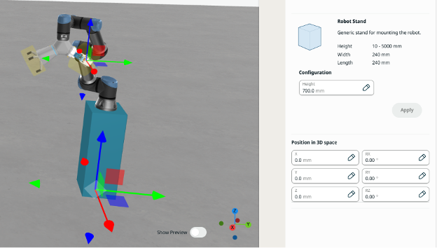
Robot stand panel and visualization
4.2.2. Conveyor
The conveyor has three different variants (small, medium, and large). It features predefined behavior where the belt runs by default and stops when the stopConveyor action is triggered by I/O. In Connections, you can find detailed information on how to configure connections and trigger the different predefined actions for various conveyor elements.
Properties
Position in 3D Space
Conveyor size
Connections:
stopConveyor (input): Signal to stop the conveyor belt
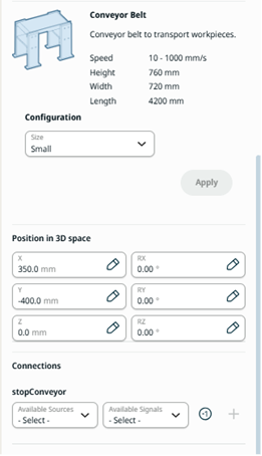
Conveyor panel
4.2.3. Robots
All released robots are available in the dropdown menu. The robot’s characteristics are displayed in the description. The robot can be positioned anywhere in the scene. Only one moving robot is supported in Studio, but users can add additional robots for layout purposes.
Properties
Position in 3D Space
Robot type
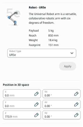
Robot panel
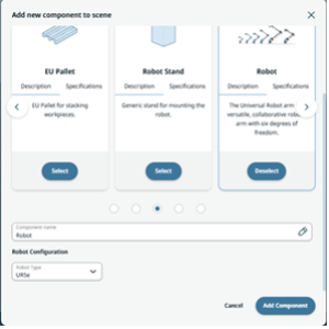
Add Robots for design purposes in the catalog
4.2.4. Sensor
The sensor is a fully configurable surface that can represent a part sensor or curtain, as its dimensions can be adjusted. When a workpiece passes by the sensor, the partDetected connection will be activated. This can be used for detecting parts and creating other automation sequences.
Properties
Dimension configuration
Position in the scene
Connections:
partDetected (output): Signal to inform that there is a collision with the sensor
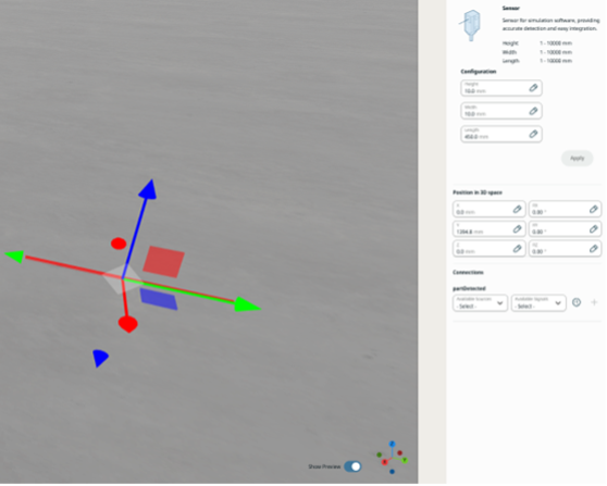
Sensor panel and visualization
4.2.5. Lathe
The lathe is a component that simulates a CNC machine. It allows users to simulate CNC machine operations. The door automatically opens and closes, the chuck can be operated, and the operation can be started.
Properties
Position in 3D Space
Connections:
SetLatheOn (input): Signal to start CNC operation
SetChuckClosed (input): Signal to close the chuck
SetDoorClosed (input): Signal to close the door
IsLatheOn (output): Signal to inform that the lathe is working
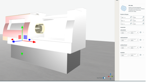
CNC machine visualization and properties
4.2.6. Control Box
The control box represents the geometry of UR control boxes used to control different robots.
Properties
Position in 3D Space
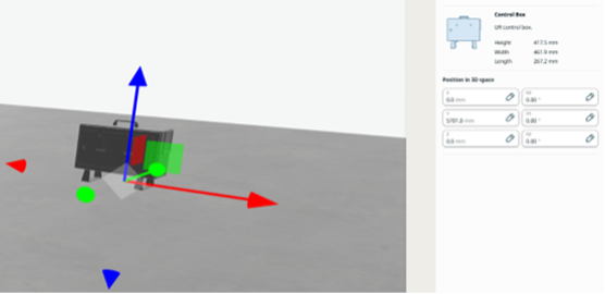
Visualization and properties of the Control Box
4.2.7. Geometry Box
To quickly emulate objects in the scene, users can generate different geometries to mimic those objects in future cells. This component creates a box.
Properties
Geometry color
Dimensions
Position in 3D Space
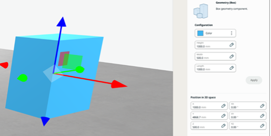
Visualization and properties of a Box
4.2.8. Geometry Cylinder
To quickly emulate objects in the scene, users can generate different geometries to mimic those objects in future cells. This component creates a cylinder.
Properties
Geometry color
Dimensions
Position in 3D Space
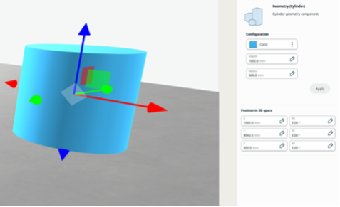
Visualization and properties of a Cylinder
4.2.9. Geometry Sphere
To quickly emulate objects in the scene, users can generate different geometries to mimic those objects in future cells. This component creates a sphere.
Properties
Geometry color
Dimensions
Position in 3D Space
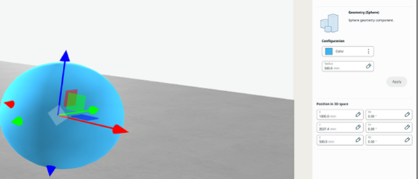
Visualization and properties of a Sphere
4.2.10. Table
Users can create a fully configurable table.
Properties
Dimensions
Position in 3D Space
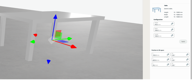
Visualization and properties of a Table
4.2.11. EU Pallet
Users can add an EU pallet and configure it with a stack height, which optimizes the pallet height so the reachability function can be adjusted.
Properties
Stack Height
Position in 3D Space
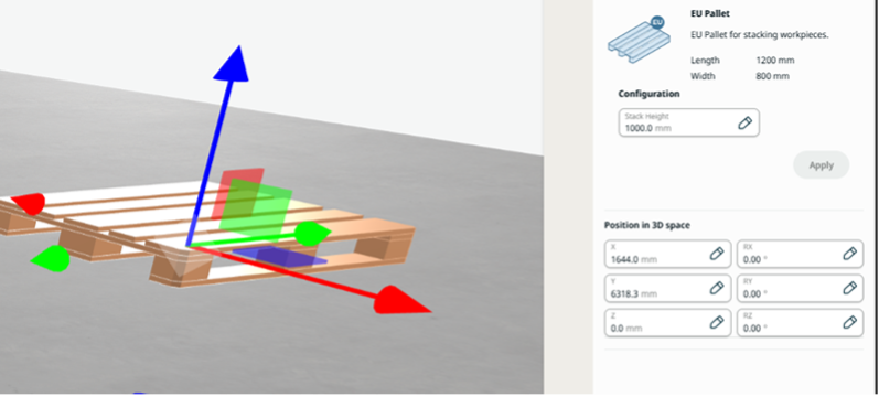
Visualization and properties of an EU pallet
4.2.12. US Pallet
Users can add a US pallet and configure it with a stack height, which optimizes the pallet height so the reachability function can be adjusted.
Properties
Stack Height
Position in 3D Space
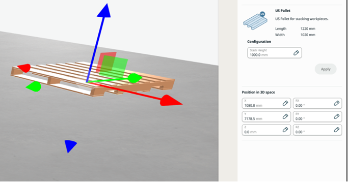
Visualization and properties of a US pallet
4.3. Zones
4.3.1. Source
The Source creates a copy of a workpiece selected in the Source Object that can be removed later from the scene using the Sink component.
Properties
Position in 3D Space
Connections:
generatePart (input): Signal to generate a copy of the selected workpiece
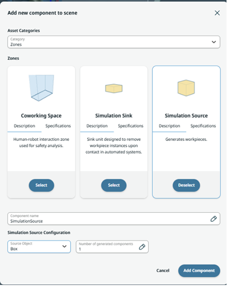
Source import
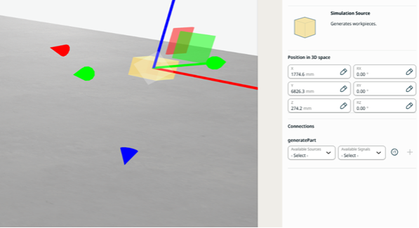
Visualization and properties of a Source
4.3.2. Sink
The Sink removes a copy of a workpiece created in the scene by the Source component when the workpiece and the sink collide.
Properties
Position in 3D Space
Dimensions
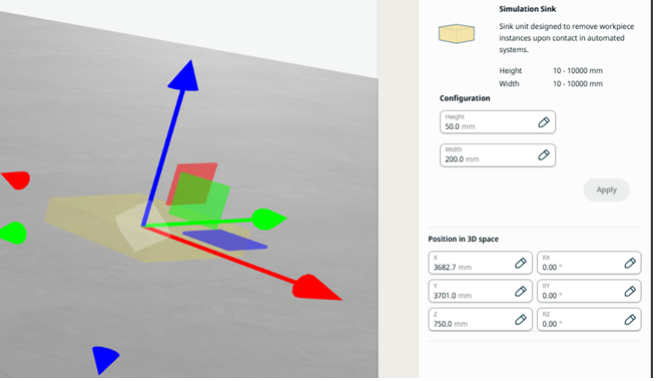
Visualization and properties of a Sink
4.4. End of Arm
All tools available in Studio exhibit similar behavior. They are positioned in space attached to the end of arm. Users can displace the tool by unchecking the Locked checkbox. This is useful when the object is slightly displaced from its origin. By default, various connections are established to the ur-tool I/O board from the robot.
In the visual representation, a yellow area indicates the gripper zones. Workpieces attach to these gripper zones when the appropriate signal (such as gripperClose) is activated.
When a gripper is imported, its Tool Center Point (TCP) is automatically created in the End Effectors application.
4.4.1. Gripper
Properties
Position in 3D Space
Connections:
gripperOpen (input): Signal to open the gripper
gripperClose (input): Signal to close the gripper
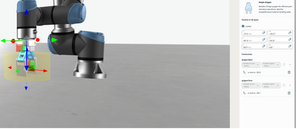
Visualization and properties of a Gripper
4.4.2. 3 Finger Gripper
Properties
Position in 3D Space
Connections:
gripperOpen (input): Signal to open the gripper
gripperClose (input): Signal to close the gripper
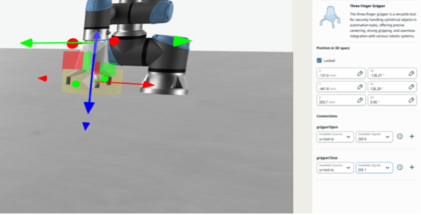
Visualization and properties of a 3 Finger Gripper
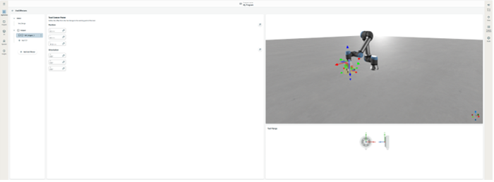
TCP created in End Effector application
4.4.3. Vacuum Gripper
Properties
Position in 3D Space
Connections:
vacuumOn (input): Signal to generate vacuum
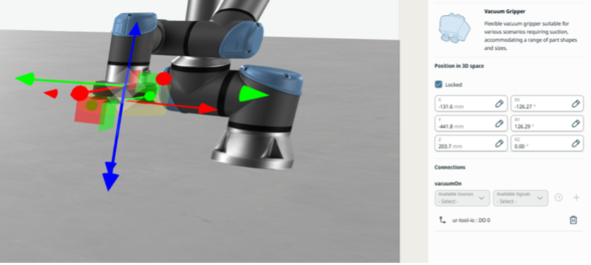
Visualization and properties of a vacuum gripper
4.4.4. Dual Mount
To use Dual Mount, users must first import two different tools in the scene.
Then, go to the catalog and add Dual Mount. In the dual mount configuration, select the two tools.
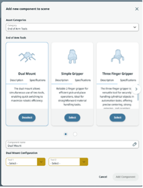
Visualization of Dual Mount configuration.
The behavior of the tools will be implemented as explained in the previous section, tool by tool.
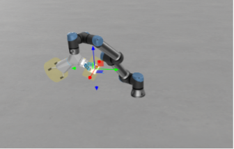
User can create a Dual Mount configuration
When both tools are imported, both TCPs are available in the End Effectors application.
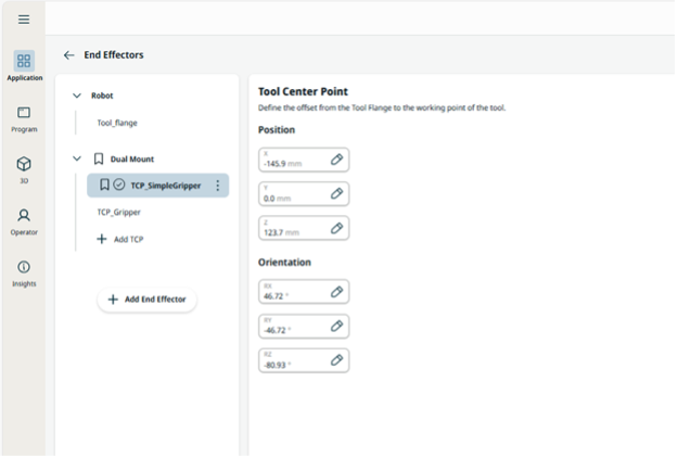
Both TCPs now appear in the End Effectors application
4.5. Workpiece
Users can load different workpieces. A workpiece is what the robot picks and drops — the part that the robot handles, welds, palletizes, etc.
By default, users can load different geometries such as blocks, boxes, and cylinders.
These workpieces have the same behaviors as geometry work cell accessories, but they behave as workpieces with physics affecting them.
Import Workpiece