Dynamic Picking
Warning
The AI Accelerator requires ROS 2 Humble, so PolyScope X 10.12.1 is the latest compatible release. PolyScope X 10.13 and later use ROS 2 Jazzy and are not currently supported.
Dynamic picking combines real-time object detection, pose estimation, and path planning to enable robots to pick objects. This capability is essential for flexible manufacturing, automated sorting, and adaptive pick-and-place operations where object positions are not predetermined.
This demo is a combination of the path planning and pose estimation functionality shown in the previous examples. Make sure you have followed the instructions in the pose estimation example documentation to train a detector and create a textured mesh for Foundation Pose to use in this example.
Running the demo
Make sure the collision model for path planning is updated and the textured mesh of your part are correctly referenced in the dynamic picking launch file.
The example should be run from inside the Jetson container which is started by running run_sdk_setup.sh as described in the SDK article.
Next launch the required ROS2 nodes on the AI Accelerator using this script:
./scripts/run_example_dynamic_picking.sh
Updating the Collision Model
This example uses the same world collision model as the basic path planning example. this yaml file can be found under /data/collision.yaml. The simple world contains just a tabletop plane and a the accessories box that the power supply for your AI Accelerator compute module came in. Place the real box on the table and then open RVIZ to view the the pose of the box and confirm the pose in the collision model matches the real physical position. When you make a change to collision.yaml the visualization of the world collision model will automatically update in RVIZ, but importantly, only the visualization updates in real time. You will need to restart the ./scripts/run_example_dynamic_picking.sh for cuMotion to take into account the updated collision geometry.
This example program does not include the commands for part attachment, so if you find that your part is colliding with the accessories box, you can either increase the height or position of the box in the collision model file for a quick fix, or dig into part attachment in the advanced path planning example.
Configuring the Polyscope Program
Warning
Before running the program it is highly encouraged to set joint angle limits as described in the Path Planning Advanced’s joint limits section in order to help streamline motion for cuMotion.
Allowing cumotion to utilize the full range of motion of all of the joints may lead to unexpected paths, such as large motions that rotate the base and elbow to a different configuration resulting in a large movement of the wrist joints. Large rotations of wrist joints can also lead to the camera cable getting tangled up and potentially damaged. It’s best to limit the range of each joint to say 30 degrees wider in either direction than is entirely needed to reach the known target positions.
If the ranges are too narrow to complete the desired task, you will see IK fail messages from the cuMotion node in the terminal and should then relax the limits until the task can be successfully completed.
Load the corresponding aia_example_dynamic_picking.urpx on your robot, and please make sure the correct detection model checkpoint is being loaded in the script in the “Before Start” section of the program.
This dynamic picking example entirely uses frames to define all of the positions the robot should move to, as opposed to waypoints. For an example using waypoints, see the pose estimation example.
This example program contains empty functions for activating, opening and closing the gripper, these need to be populated with the relevant nodes for your gripper (likely provided by the URCap for the gripper).
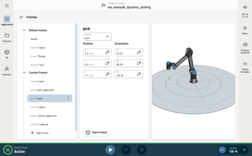
The program contains a Detection script that sets the “part” frame at the origin of the textured mesh provided, but this is not usually where we want to move our TCP to directly. To define how we want to pick the part we will define a pick offset relative to the part origin.
Inside the Frames application node you will find a number of Custom Frames - pick & pick_approach, place & place_approach, part and capture. For the best demonstration of the path planning involved, it’s recommended to teach the capture and pick on one side of the accessory box, and the place on the other side, so the robot will move over or around the box to the place position.
First set the capture frame to a fixed position where you want to capture the images for pose estimation from.
Next drag the speed slider down to 10% and hit play and wait for the pose estimation to complete. When it is successful you should see the poses variable under the global variables menu (in the right side bar) populated with a pose. You can also use RVIZ to view the resulting pose and confirm it is correct. RVIZ will utilize the mesh as a marker to show where FoundationPose thinks the part is.
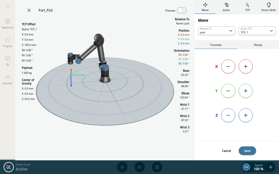
As soon as the pose estimate has completed stop the program, and teach the pick frame. It’s important that you don’t move the part at all (don’t nudge it with the gripper) while teaching this position. You can use freedrive for this, if you need to jog the robot in base or tool frames, make sure you set the relative frame back to part before saving the waypoint. The pick_approach is already defined at a fixed distance above the part, so there’s no need to change this.
Now run the program again, the robot should pick the part and retract to the pick_approach position. Now stop the program with the part in hand and teach a fixed place frame. Once again the place_approach is already defined above the place frame.
Now you are ready to run the program in full. It’s a good idea to run it at low speed first in case anything unexpected occurs. It will estimate the pose of the part, pick it, and then place it. The program will run in a loop, so you can manually move the part back to the capture area while the robot is moving back to the capture point.
When you have done this, hit play and the pose estimation pipeline will run, resulting in an estimation of the 6 degree of freedom pose of your part in the robot base frame. The robot will leverage cuMotion path planning to plan collision free paths around the workspace to get between the fixed image capture, dynamic pick and fixed place positions. Dynamic planning will be used to get to the approach point above the pick and place positions, and then a fixed distance move into contact motion used to move to the pick position, to avoid protective stops in case of colliding with the part.