Path Planning Advanced
Warning
The AI Accelerator requires ROS 2 Humble, so PolyScope X 10.12.1 is the latest compatible release. PolyScope X 10.13 and later use ROS 2 Jazzy and are not currently supported.
Path planning is a critical capability in robotics that enables robots to navigate safely and efficiently through complex environments while avoiding obstacles. The AI Accelerator integrates Isaac ROS cuMotion as the underlying advanced path planning technology to provide collision-free motion planning for robot applications.
This demo shows how to configure and use path planning with the AI Accelerator for safe robot navigation and obstacle avoidance in complex workspaces.
Prerequisites
AI Accelerator hardware
Universal Robot with AI Accelerator and AIA SDK URCaps installed
Access to the compute module terminal
Overview
The example should be run from inside the Jetson container which is started by running run_sdk_setup.sh as described in the SDK article.
Objective: Configure and use path planning for safe robot navigation and obstacle avoidance in complex workspaces.
What you’ll achieve:
Configure the robot
Configure and visualize collision models for path planning
Start path planning services on AI Accelerator
Configure the joint limits
Integrate path planning with robot programs
Configure Robot
The path planning system needs to know that type of robot running on the system. This can be configured by editing the robot_type entry in the config.yaml file in the config folder. Currently, the supported robot types are ur3e, ur5e, ur10e, and ur16e.
Configure and Visualize Collision Models
To use path planning, we need to first configure the collision models of the obstacles in the workspace as well as those of the tool mounted on the robot and the part the robot will carry. The collision models are defined in a yaml file. The path to the yaml file is specified in the collision_file entry in the config.yaml file. For this example, collision_file should point to "/workspaces/isaac_ros-dev/data/collision_advanced.yaml".
To visualize the collision models, we need to run rviz and collision_model_visualizer from the terminal inside the container. In one terminal, run
./scripts/run_rviz.sh
This will start an RViz window that listens to the joint states from the robot whose serial number is speicified in config.yaml.
In another terminal, run
source install/setup.bash
source install_isaac_pkgs/setup.bash
ros2 launch ur_cumotion collision_model_visualizer.launch.py
This will read the yaml file specified in config.yaml and publishes the collision models defined in the collision_advanced.yaml file to be displayed in RViz. Note that the user can live edit collision_advanced.yaml and whenever it is saved, the changes will immediately be reflected and displayed in RViz.
Alternatively, you can run
./scripts/run_example_path_planning.sh
This will launch the collision_model_visualizer node as well as the path planner node.
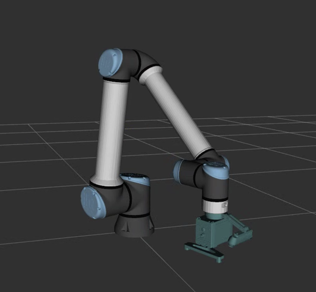
To add collision spheres for the tools, the user can add to tool_collision_spheres of collision_advanced.yaml as shown in the example below. In this example, we define the collision spheres for the tools attached to the robot’s tool flange, including the camera and a gripper. In order to make configuring the tool spheres easier, the user can also add the mesh of the tools in tool_meshes section, allowing visualization of both the tool meshes and tool collision spheres at the same time. Note that only the tool collision spheres, and not tool meshes, are used in path planning calculations. Note also that the gripper.stl file itself is not provided with the SDK and is only referenced here in the example for illustration purposes. The user should suuply their own gripper mesh file in the STL format.
# tool_meshes are used to visualize the tool in RViz to make it easier to create tool_collision_spheres
# Not used by cuMotion for collision checking
tool_meshes:
 tool:
   file_path: "/workspaces/isaac_ros-dev/data/models/gripper.stl"
   position: [0, 0, 0.0125]
   rotation: [0, 0, 0]
   scale: [0.001, 0.001, 0.001]

# Collision objects for tool represented by spheres
# Each tool has a position and rotation that is relative to the flange
# position: [x, y, z] position of the tool frame in meters
# rotation: [rx, ry, rz] XYZ Euler angles in degrees representing the rotation of the tool frame
# center: [x, y, z] position of the sphere in meters relative to the tool frame
# radius: radius of the sphere in meters
# The spheres will be transformed to the flange frame and then combined together and sent
# to cuMotion for collision checking
tool_collision_spheres:
  bracket:
    position: [0, 0, 0]
    rotation: [0, 0, 0]
    spheres:
      - center: [0, -0.04, 0]
        radius: 0.02
  camera:
    position: [0, -0.12, 0.03]
    rotation: [-25, 0, 0]
    spheres:
      - center: [0, 0.05, 0]
        radius: 0.02
      - center: [0, -0.0, 0]
        radius: 0.02
      - center: [0, 0.02, 0]
        radius: 0.02
      - center: [0.04, 0, 0.03]
        radius: 0.03
      - center: [0, 0, 0.03]
        radius: 0.03
      - center: [-0.04, 0, 0.03]
        radius: 0.03
  gripper:
    position: [0, 0, 0.065]
    rotation: [0, 0, 0]
    spheres:
      - center: [0.03, 0, 0]
        radius: 0.065
      - center: [-0.03, 0, 0]
        radius: 0.065
  finger_1:
    position: [0.08, 0, 0.12]
    rotation: [0, 0, 0]
    spheres:
      - center: [0, 0.0, 0]
        radius: 0.02
      - center: [0, 0.05, 0]
        radius: 0.02
      - center: [0, 0, 0]
        radius: 0.02
      - center: [0, -0.04, 0]
        radius: 0.02
      - center: [0, -0.08, 0]
        radius: 0.02
  finger_2:
    position: [-0.09, 0, 0.12]
    rotation: [0, 0, 0]
    spheres:
      - center: [0, 0, 0]
        radius: 0.02
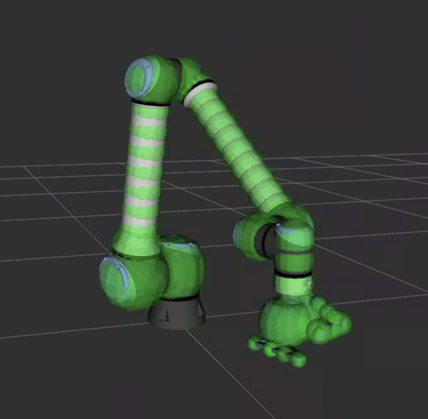
The image below shows the UR10e robot with the tools whose mesh is provided in the form of an STL file while the following image shows the oollision spheres of the UR10e robot (internally defined and cannot be modified) and the tools.
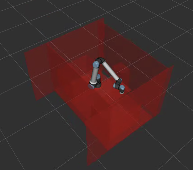
The user can define collision models of obstacles inside the workspace as cuboids or boxes in world_cuboids section of collision_advanced.yaml. Below is a snippet that defines walls, stand, ground, and two bins as obstacles with visualization of them shown in the image that follows.
# World collision objects represented by cuboids (or boxes)
# dims: [x, y, z] dimensions of the box in meters
# position: [x, y, z] position of the box in meters
# rotation: [rx, ry, rz] XYZ Euler angles in degrees representing the rotation of the box
world_cuboids:
  workspace:
    position: [0, 0, 0]
    rotation: [0, 0, 0]
    cuboids:
    # right_wall
      - dims: [2., 0.01, 1.44]
        position: [0., -1.0, 0.]
        rotation: [0, 0, 0]
    # left_wall
      - dims: [2., 0.01, 1.44]
        position: [0., 1.0, 0.]
        rotation: [0, 0, 0]
    # front_wall:
      - dims: [0.01, 2., 1.44]
        position: [-0.5, 0., 0.]
        rotation: [0, 0, 0]
    # back_wall:
      - dims: [0.01, 2., 1.44]
        position: [0.85, 0.0, 0.]
        rotation: [0, 0, 0]
    # ground:
      - dims: [1.25, 2., 0.01]
        position: [0.125, 0., -0.7]
        rotation: [0, 0, 0]
    # stand:
      - dims: [1.25, 0.6, 0.01]
        position: [0.125, 0., -0.44]
        rotation: [0, 0, 0]

  jig_stand:
    position: [0.67, 0, -0.32]
    rotation: [0, 0, 0]
    cuboids:
      - dims: [0.25, 0.3, 0.8]
        position: [0, 0, 0]
        rotation: [0, 0, 0]

  right_box:
    position: [0.02, 0.03, 0]
    rotation: [0, 0, 0]
    cuboids:
    # rbox_right_wall:
      - dims: [0.780, 0.01, 0.575]
        position: [-0.02, -0.94, -0.3025]
        rotation: [0, 0, 0]
    # rbox_left_wall:
      - dims: [0.780, 0.01, 0.575]
        position: [-0.02, -0.345, -0.3025]
        rotation: [0, 0, 0]
    # rbox_front_wall:
      - dims: [0.585, 0.01, 0.575]
        position: [-0.415, -0.6375, -0.3025]
        rotation: [0, 0, 90]
    # rbox_back_wall:
      - dims: [0.585, 0.01, 0.575]
        position: [0.375, -0.6375, -0.3025]
        rotation: [0, 0, 90]
    # rbox_ground:
      - dims: [0.780, 0.585, 0.01]
        position: [0, -0.6175, -0.63]
        rotation: [0, 0, 0]

  left_box:
    position: [0.02, -0.02, 0]
    rotation: [0, 0, 0]
    cuboids:
    # lbox_right_wall:
      - dims: [0.780, 0.01, 0.575]
        position: [-0.02, 0.93, -0.3025]
        rotation: [0, 0, 0]
    # lbox_left_wall:
      - dims: [0.780, 0.01, 0.575]
        position: [-0.02, 0.345, -0.3025]
        rotation: [0, 0, 0]
    # lbox_front_wall:
      - dims: [0.585, 0.01, 0.575]
        position: [-0.405, 0.6375, -0.3025]
        rotation: [0, 0, 90]
    # lbox_back_wall:
      - dims: [0.585, 0.01, 0.575]
        position: [0.385, 0.6375, -0.3025]
        rotation: [0, 0, 90]
    # lbox_ground:
      - dims: [0.780, 0.585, 0.01]
        position: [0, 0.6175, -0.63]
        rotation: [0, 0, 0]
Note that the path planner needs at least one cuboid to be defined, otherwise it will fail to initialize. Typically, this can be a cuboid that cover the table, the stand, or that floor on which the robot is mounted.
Starting the Path Planning System
Once the collision models have been properly configured, we can start the path planner by running the following command in the terminal:
./scripts/run_example_path_planning.sh
If everything goes well, after a monment, we should see the following message that signifies that the path planner is initialized and ready.
cuMotion is ready for planning queries!
Configure the Joint Limits
By default, the joint limits used in path planning are -180 to +180 degrees for the elbow joint and -360 to +360 degrees for all other joints. These large joint ranges, however, can result in the robot, especially the wrist joints, to move in winding motions that could damage the camera’s cable. To prevent this, we can change the joint limits to decrease the joint ranges. We can do this in two ways.
Manually editing the joint limits
The config.yaml file contain a section named urdf_folder. This is the location to which the urdf file used for path planning will be copied after the path planner is run for the first time. The user can open the urdf file (e.g. ur10e.urdf) and manually editing the joint limit values directly and save the file and then re-run the path planner.
Changing the joint limits with ROS2 service
Alternatively, the user can also issue a ROS2 service call command to change the joint limits. For example, the following command, where 192168000100 is the IP address of AI Accelerator formatted to have 12 digits. In this example, the IP address is 192.168.0.100. Replace it as necessary.
ros2 service call /IP192168000100/ur_cumotion/set_joint_limits ur_cumotion_msgs/srv/SetJointLimits "{joint_names:['shoulder_pan_joint'], lower_limits:[-3.14159], upper_limits:[3.14159]}"
will change the first joint limit (shoulder_pan_joint) to +/-180 degrees. The valid joint names are 'shoulder_pan_joint', 'shoulder_lift_joint', 'elbow_joint', 'wrist_1_joint', 'wrist_2_joint', and 'wrist_3_joint'. Note that one of lower_limits and upper_limits can be omitted or empty. If it’s specified, however, it needs to have the same number of elements as joint_names.
If you want to change the limits of all 6 joints, you can omit joint_names like this:
ros2 service call /IP192168000100/ur_cumotion/set_joint_limits ur_cumotion_msgs/srv/SetJointLimits "{lower_limits:[-3.14159, -3.14159, -3.14159, -3.14159, -3.14159, -3.14159]}"
The command above will change the lower limits of all 6 joints to -180 degrees, while leaving the upper limits unchanged.
Because ROS2 services can be called in URScript, the user can also call the set_joint_limits with URScript, instead of from the terminal as shown in the example below. Note that the AI Accelerator and AI Accelerator SDK URCaps must first be installed and that ARK_ROS2Namespace is defined when IP address is set in the AI Accerator URCap.
    joint_limit_client = ros_service_client_factory(ARK_ROS2Namespace + "/ur_cumotion/set_joint_limits", "ur_cumotion_msgs/srv/SetJointLimits")
    # set lower and upper limits of all six joints
    joint_limits = struct(joint_names=[], lower_limits=[-3.14159, -3.14159, -3.14159, -3.14159, -3.14159, -3.14159], upper_limits=[3.14159, 3.14159, 3.14159, 3.14159, 3.14159, 3.14159])
    joint_limit_client.call(joint_limits)
Note that in order to change the joint limits with ROS2 service, the path planner needs to already be running.
Path Planning Usage
Single Shot Planning
After staring the path planner on AI Accelerator, the user can use URScript API to plan and execute collision-free paths.
First, we need to initialize the path planning service client by calling
ark_path_planning_init()
This should be done in the Before Start section of a program. Then, in the Main Program section, the user can call either ark_move_path_plan or ark_move_path_plan_js to plan a path to a single goal and then execute it. For example, the following command moves the robot to a tool pose at [-0.08, -0.61, -0.03, -0.3, 3.14, 0.77] defined in the UR pose convention.
ark_move_path_plan("point_1", p[-0.08, -0.61, -0.03, -0.3, 3.14, 0.77], 1.0, False)
while this one moves the robot to a joint configuration [1.6, -2.2, -2.2, -0.8, 1.5, 0] radians for the six joints.
ark_move_path_plan_js("point_2", [1.6, -2.2, -2.2, -0.8, 1.5, 0], 1.0, False)
Object Attachment
In a typical pick and place application, the robot will need to pick up a part or an object. When that happens, we need to take into account the shape of the part or object that the robot carries in path planning calculations. This is accomplished in two steps. First, we need to define the collision spheres of the part by adding them to the attached_objects section of the collision_advanced.yaml file. The following snippet shows an example of defining two spheres for the part named part_1.
# attached_objects define the collision spheres for objects that can be grasped/released by the robot
# For each attached object,
# position and rotation are relative to the flange
# position: [x, y, z] position of the attached_object frame in meters
# rotation: [rx, ry, rz] XYZ Euler angles in degrees representing the rotation of the attached_object frame
# centers and radii are in the attached_object frame
attached_objects:
  part_1:
    position: [0, 0, 0.15]
    rotation: [0, 0, 0]
    spheres:
      - center: [0.05, -0.12, 0]
        radius: 0.01
      - center: [0.06, -0.08, 0]
        radius: 0.01
Do not forget to restart the path planner after modifying the collision_advanced.yaml file for the change to take effect.
After the part’s collision spheres are defined, we can tell the path planner to dynamically include or exclude them during planning via a ROS2 service. To do this in URScript, first we need to initialize the ROS2 service client with the following command in Before Start section.
global attach_object_client = ros_service_client_factory(ARK_ROS2Namespace + "/ur_cumotion/attach_object", "ur_cumotion_msgs/srv/AttachObject")
Then, in the Main Program portion, we can all the following to include part_1’s collision spheres during planning, i.e. after the robot has picked up the part. Note that the value passed as object_name must be defined in the collision_advanced.yaml file.
attach_object_client.call(struct(attach_object=True, object_name="part_1"))
If object_name is invalid, then the response of this call will indicate a failure which can then be checked as shown in the following script.
att_resp = attach_object_client.call(struct(attach_object=True, object_name="part_2"))
if att_resp.success == False:
    popup("Failed to attach object")
    halt
end
When this happens, the path planner will also print an error message in the console.
No spheres found for attached object: part_2
To exclude them after the robot has dropped the part, use the following command
attach_object_client.call(struct(attach_object=False, object_name=""))
Note that when attach_object is set to False, although object_name can be set to anything (e.g. empty string in this case), it cannot be omitted or syntax error will occur.
Troubleshooting of Path Planning Failures
There are many reasons the path planner can fail. When it does, an error message with an error code will be printed in the console. Common error codes include the following.
IK_FAIL
Motion planning failed wih status: MotionGenStatus.IK_FAIL
This can happen if
the goal pose specified in
ark_move_path_plancall is unreachable (i.e. outside the robot’s reach)the goal pose specified in
ark_move_path_planis in collisionthe goal joints specified in
ark_move_path_plan_jsare not within the joint limits
INVALID_START_STATE_JOINT_LIMITS
Motion planning failed wih status: MotionGenStatus.INVALID_START_STATE_JOINT_LIMITS
This happens when the current joint angles are outside of the path planner’s joint limits (which can be more restricted than the robot’s physical joint limits).
INVALID_START_STATE_WORLD_COLLISION or INVALID_START_STATE_SELF_COLLISION
Motion planning failed wih status: MotionGenStatus.INVALID_START_STATE_WORLD_COLLISION
This happens when the robot is currently in collision either with the environment or with itself.
GRAPH_FAIL
Joint space planning failed with status MotionGenStatus.GRAPH_FAIL
This can happen if
the joint goal specified in
ark_move_path_plan_jsis in collisionthe path planner fails to find a collision-free path
TRAJOPT_FAIL or FINETUNE_TRAJOPT_FAIL
This happens when the path planner fails to find an optimized collision-free path. It can happen when planning a move from and to a position that is difficult to reach (i.e. inside a bin). One solution is to add an intermediate point and break up the path into two segments.
Additional Resources
URScript API Reference: See path planning functions in the URScript API documentation.
Robot Programming Examples: Check the AI Accelerator SDK for additional examples.