Pose Estimation
Warning
The AI Accelerator requires ROS 2 Humble, so PolyScope X 10.12.1 is the latest compatible release. PolyScope X 10.13 and later use ROS 2 Jazzy and are not currently supported.
Six-degree-of-freedom (6DOF) pose estimation provides precise 3D position and orientation information for objects in the robot workspace. This capability is essential for accurate pick-and-place operations, object manipulation, and spatial reasoning in robotics applications. The AI Accelerator integrates advanced pose estimation algorithms to provide real-time 6DOF pose data.
This demo shows how to configure and use 6DOF pose estimation with the AI Accelerator for precise object manipulation and spatial reasoning applications.
Prerequisites
Foundation pose requires the following:
A detection model trained on the desired part, that identifies where the part is in the input images.
RBG and depth images, with bounding box or preferably segmentation of the part obtained using the detection model.
An accurately dimensioned textured mesh of the part.
These can be created according to the below steps:
Training a Detector
Use the Detection Trainer to capture and annotate image samples and train the detector
Generating a Textured Mesh
There are a number of ways to create this mesh, but for testing purposes the most straightforward way is to use an iPhone app called AR Code or similar app to scan the physical part (for best results an iPhone pro should be used). This will product a USD file, which can then be converted to an OBJ file with image texture using one of many widely available free online tools.
Once the OBJ is obtained, place it in the ros/data directory on the AIA and run the helper_scripts/center_mesh.py tool inside the container to move the origin of the mesh to the center of the volume to ensure best results with foundation pose.
Warning
The example launch file for pose estimation includes a constraint on the pose of the mesh. For scenarios where the workpiece is placed on a tabletop and can only be in a small range of possible orientations, this significantly speeds up pose estimation, however if the orientation is not within this range, it can cause pose estimation to fail.
The example assumes the Y axis of the mesh is pointing up (parallel to the robot base frame +z). To remove (or adjust) this constraint, look at ros/launch/aia_example_pose_estimation.launch.py and under the fp_node, comment out or modify this line:
'fixed_axis_angles': "['x_-90', 'y_0', 'z_0', 'z_30', 'z_60', 'z_90', 'z_120', 'z_150', 'z_180', 'z_210', 'z_240', 'z_270', 'z_300', 'z_330']",
Running the example
The example should be run from inside the Jetson container which is started by running run_sdk_setup.sh as described in the SDK article.
Open the aia_example_pose_estimation.launch.py file and edit the launch arguments to point to the newly generated OBJ and JPG or PNG texture files.
Next launch the required ROS2 nodes on the AI Accelerator using this script:
./scripts/run_example_pose_estimation.sh
Then load the corresponding aia_example_path_planning.urpx on your robot.
The detection trainer will have generated a checkpoint model under ros/data/models/rtdetr_active on the AI Accelerator. Be sure to update the script in the before start section of the Polyscope X program to load in this checkpoint.
Configuring the Polyscope Program
This pose estimation example uses a waypoint defined relative to the part frame to teach the pick offset for the part. For an example using purely frames, see the dynamic picking example.
This example program contains empty functions for activating, opening and closing the gripper, these need to be populated with the relevant nodes for your gripper (likely provided by the URCap for the gripper).
The program contains a Detection script that sets the “part” frame at the origin of the textured mesh provided, but this is not usually where we want to move our TCP to directly. To define how we want to pick the part we will define a pick offset relative to the part origin.
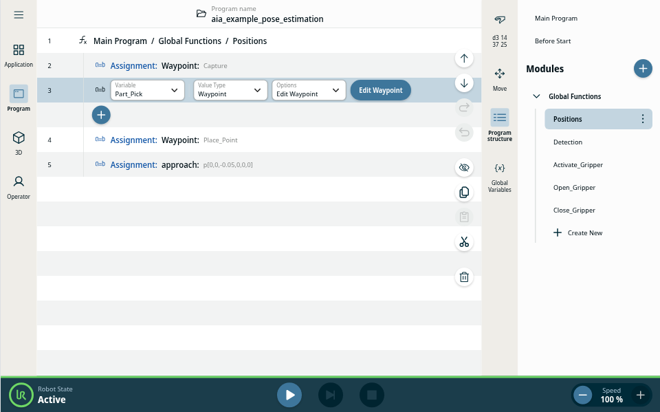
Inside the Positions Function you will find 3 waypoints - Capture, Part_Pick and Place_Point, as well as an approach offset variable is used to define an approach/exit point above the part:
First set the Capture point to a fixed position where you want to capture the images for pose estimation from.
Next drag the speed slider down to 10%, under operator toggle configuration to True, and hit play and wait for the pose estimation to complete. When it is successful you should see the poses variable under the global variables menu (in the right side bar) populated with a pose. You can also use RVIZ to view the resulting pose and confirm it is correct. RVIZ will utilize the mesh as a marker to show where FoundationPose thinks the part is.
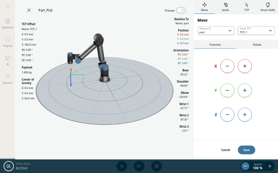
As soon as the pose estimate has completed stop the program, and teach the Part_Pick waypoint. It’s important that you don’t move the part at all (don’t nudge it with the gripper) while teaching this position. You can use freedrive for this, if you need to jog the robot in base or tool frames, make sure you set the relative frame back to part before saving the waypoint:
Now run the program again, the robot should pick the part and retract to the approach position. Now stop the program with the part in hand and teach a fixed Place_Point.
Now you are ready to run the program in full. It’s a good idea to run it at low speed first in case anything unexpected occurs. It will estimate the pose of the part, pick it, and then place it. The program will run in a loop, so you can manually move the part back to the capture area while the robot is moving back to the capture point.